Overview
In this section, we will show you the basic steps to configure a multi-channel (non-blanket) wireless network, through a quick tour. The steps include adding APs to the management database, putting APs on floor maps and scheduling AWC (Autonomous Wave Control) operation.
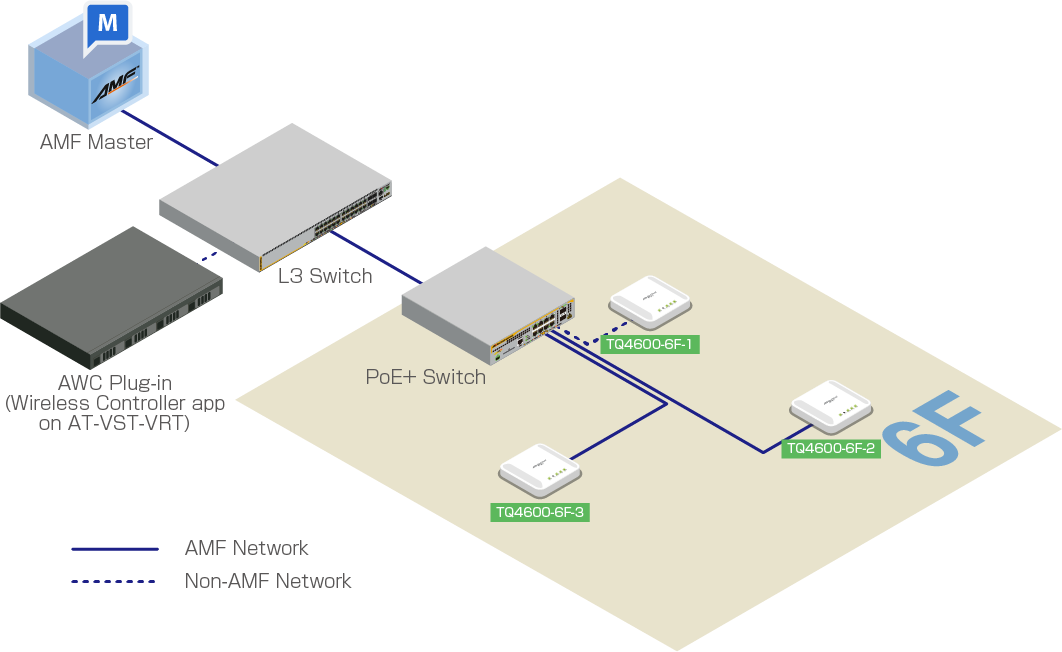
For simplicity, we assume that we are going to create the following network:
| Device Name | Device Name | Description |
|---|---|---|
| AMF Master | AT-VAA | Running AMF Cloud |
| AlliedWare Plus Layer 3 Switch | IP Address: 192.168.1.1 Configured as a DHCP/NTP server |
|
| PoE+ AlliedWare Plus Switch | Supplying power with PoE+ On its ports for connecting wireless APs, VLAN 1 is the native VLAN and VLAN 100 is the only tagged VLAN that is allowed. |
|
| TQ4600 | TQ4600-6F-1 | IP Address: 192.168.1.100 MAC Address: 00:00:5E:00:53:00 Not joining the AMF network |
| TQ4600 | TQ4600-6F-2 | IP Address: 192.168.1.200 (statically assigned by DHCP server) MAC Address: 00:00:5E:00:53:20 Already joined the AMF network as a guest device |
| TQ4600 | TQ4600-6F-3 | IP Address: 192.168.1.201 (statically assigned by DHCP server) MAC Address: 00:00:5E:00:53:40 Already joined the AMF network as a guest device |
| Wireless Controller application container | AWC Plug-in |
We assume that the following configuration items have been completed:
- The AMF network has been added to the management database of Vista Manager EX.
- The PoE+ switch has been properly configured to accommodate APs as guest devices.
- The L3 switch has been configured with two VLANs, vlan1 (192.168.1.0/24) as the native VLAN and vlan100 (192.168.100.0/24) as the VLAN for wireless clients. DHCP pool for each VLAN was also setup.
- The PoE+ switch ports for wireless APs (and other required ports) have been configured with vlan1 as the native VLAN and vlan100 as the tagged VLAN for normal traffic.
- The APs have been configured separately with their IP addresses.
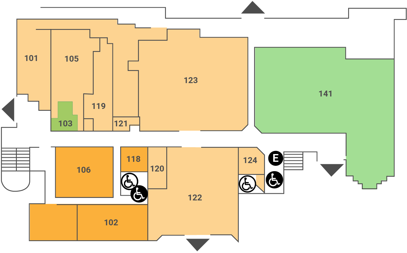
We also assume that we prepared the following image for the floor map.
Configure External IP Address for AWC Plug-in
Before using the AWC Plug-in to manage wireless APs, please register first the IP address of the Wireless Controller application (AWC Plug-in) on the VST-VRT as an external IP address in the System Setting screen of the AWC Plug-in.If you have already configured the external IP address of the AWC plug-in correctly, this step is not necessary.
- Click on System Setting from the AWC Plug-in menu.
The "System Setting" screen appears.
- In the "External IP Address for AWC plug-in" under "IP Address Settings", select the IP address of the Wireless Controller application (i.e., AWC Plug-in) on the VST-VRT from the dropdown list.
- Click on the "Save" button to the right side of "IP Address Settings".
02 Nov 2021 16:59