3D Floor Map [Wireless Status View]
To display the 3D floor map view, select a specific management group from the management group drop-down menu on the floor map List screen, and then check any floor maps from the Floor Map List on the right.
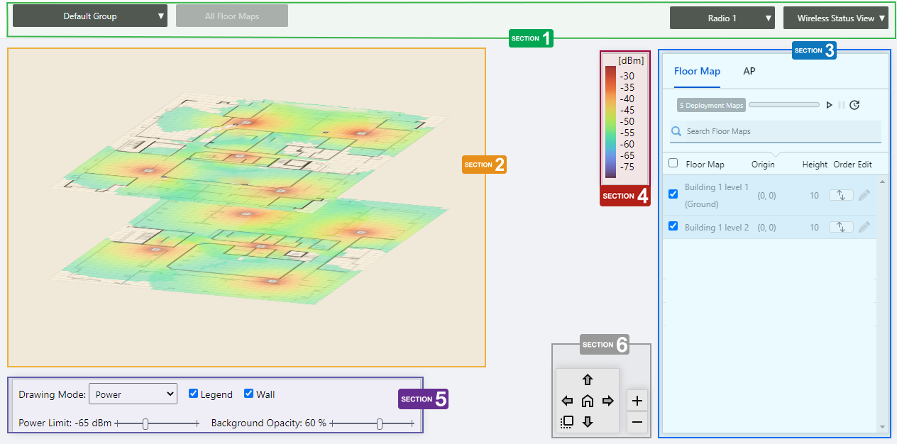
Section 1
| Item Name | Description |
|---|---|
| Management Group drop-down menu | You can narrow down the floor map to be displayed. If you change the currently selected management group, the 3D Floor Map view will be canceled and you will return to the Floor Map List panel view. |
| Floor Map drop-down menu | Disabled on 3D floor map. |
| Radio dropdown menu | Lets you select a radio band to show on the map, from Radio 1, 2 or 3. |
| View Selection dropdown menu | Lets you change what information is displayed on the Floor Map Details screen.
|
Section 2
The selected floor map will be displayed layer by layer.
The display angle of the floor maps can be controlled using the angle adjustment button at the bottom right.
Each floor map displays the icons of the APs placed in the individual floor map detail screen, a heat map showing the channel or signal reach and strength in color around the wireless APs, and the areas or walls you have created.
The drawing mode of the heat map can be selected from the floor map control.
NoteWhen you place your mouse cursor on an AP, the management information of the AP will pop up.Even between wireless APs operating at the same radio strength, the size of output circle on the heat map may vary depending on the installation location and other factors.
- Wireless AP Name
- MAC Address
- IP Address
Section 3
Floor maps / wireless AP list will be displayed. You can switch between the floor map list and the wireless AP list using the tabs at the top of the list.
Place the mouse pointer on any line in the floor map list to highlight the corresponding floor map in the layered view.
Also, when you place the mouse pointer on any line of the wireless AP list, the corresponding wireless AP icon on the floor map will be highlighted with a blue dot.
| Item Name | Description |
|---|---|
| Header | |
| Floor Map/AP Tab | Switches the contents of the list. |
| Floor Map List | |
| X Deployment Map | Displays the number of floor maps that belong to the selected management group. |
| Refresh Timer | Shows the status of the timer that automatically refreshes the page with the blue progress bar. The list is automatically refreshed at the interval configured on "Refresh Rates" > "Floor MAP (Wireless Status)" in the User Management menu. (The default is 1 minute.) In the 3D floor maps view, the resume/pause automatic update buttons and the manual update button are displayed along with a progress bar. By default, automatic updates are paused. |
| Search Floor Map | Disabled on 3D floor map. |
| Checkbox | Check this box if you want to select the floor map as the display target. |
| Floor Map | The floor map names belonging to the selected management group will be displayed. |
| Origin | Displays the upper left coordinate of the floor map image. |
| Height | Displays the set ceiling height of the floor. |
| Order | You can change the order of the floor map by clicking and holding the mouse pointer up or down. |
| Edit (pencil icon) | The "Edit 3D Map Settings" dialog box will appear. ◼ Edit 3D Map Settings 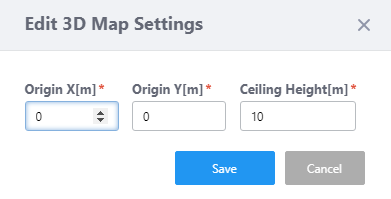
|
| AP list | |
| X AP | Shows the number of APs placed on the floor map. |
| Refresh Timer | Shows the status of the timer that automatically refreshes the page with the blue progress bar. The list is automatically refreshed at the interval configured on "Refresh Rates" > "Floor MAP (Wireless Status)" in the User Management menu. (The default is 1 minute.) In the 3D floor maps view, the resume/pause automatic update buttons and the manual update button are displayed along with a progress bar. By default, automatic updates are paused. |
| "Search" box | Entries in the list can be filtered by entering a partial string in the search box. Displays the items among the current display targets that contain the string entered in this field in either " Device Name" or "Floor Map Name". To remove the filter, delete the string from the search field and press enter. NoteThe search is case-sensitive. |
| Device Name | Shows the name given to the AP. |
| Floor Map Name | The name of the floor map the AP belongs to is displayed. |
| Management Status | Shows the Management Status of the AP. |
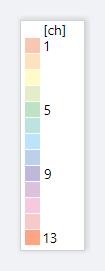
Section 4
It shows the relationship between colors and signal strength or channels.
The legend can be made invisible or visible by using a checkbox in the floor map control section at the bottom of the page.
Color conventions depend on the floor map drawing mode.
- Power
- Channel
Section 5
| Item Name | Description |
|---|---|
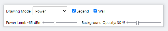
| Drawing Mode | Lets you select what to show on the heatmap. Options are power (signal strength) and channel. |
| Legend | Lets you enable or disable the legend. Check to display. |
| Wall | Lets you choose whether to display the walls if walls have been created on the floor map (using the Edit Wall page). Check to display.NoteIf walls have been defined, attenuation by the walls takes effect over the heat map even if this control is left unchecked. |
| Power Limit | Specify the minimum signal strength to show in colors on the heatmap. |
| Opacity | Specify the opacity of the floor map background image. |
Section 6
Adjusts the display size and angle of the map.
- Zoom In/Out buttons
You can zoom in (+) or zoom out (-) of the floor map display. You can also use the mouse wheel scroll to zoom in or out.

- Angle adjustment button
Only in the layered view, the angle at which the floor map is displayed can be adjusted using the arrow buttons.
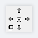
- Up/Down arrows: Adjust the vertical (pitch) angle.
- Left/Right arrows: Adjust the horizontal rotation (yaw) angle.
- Plan view button (left-bottom): All floors are superimposed and displayed as a plan view looking down from above.
- Home position (center): Returns the angle of view to the initial state.
- Up/Down arrows: Adjust the vertical (pitch) angle.
04 Jul 2023 13:01