Overview
In this section, we will show you the basic steps to configure an AWC-CB (AWC-Channel Blanket) wireless network, through a quick tour.
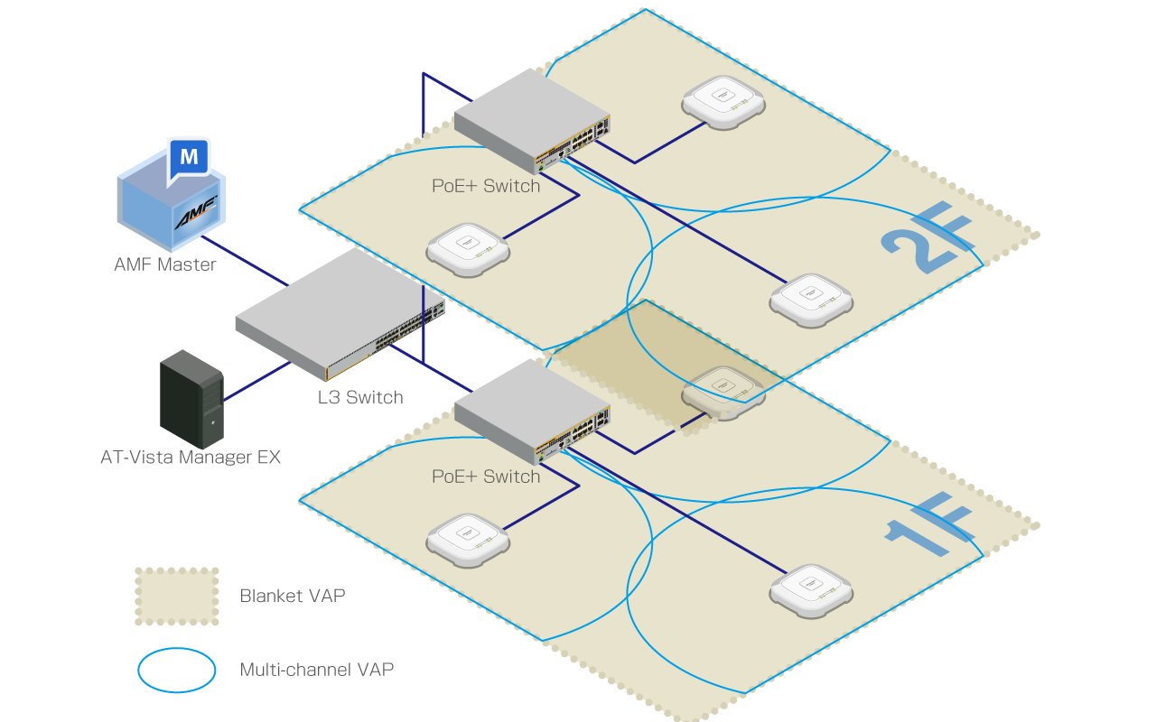
Here we assume the following configuration:
- There are two floors (1F and 2F).
- On both floors, we will operate wireless networks for employee PCs and mobile devices.
- On the first floor, we will also operate a separate wireless network for guests.
| Device Name | Node Name | IP Address | MAC Address | Role | |
|---|---|---|---|---|---|
| AMF Master | AT-VAA | AMF Cloud | |||
| PC | Vista Manager EX | ||||
| AlliedWare Plus Layer 3 Switch | 192.168.1.1 | DHCP/NTP Server | |||
| 1F | PoE+ AlliedWare Plus Switch | x230-1F | Supplying power with PoE+ | ||
| TQ5403 | TQ5403-1F-1 | 192.168.1.100 | 00:00:5E:00:53:00 | AMF Guest Node | |
| TQ5403-1F-2 | 192.168.1.101 | 00:00:5E:00:53:20 | |||
| TQ5403-1F-3 | 192.168.1.102 | 00:00:5E:00:53:40 | |||
| 2F | PoE+ AlliedWare Plus Switch | x230-2F | Supplying power with PoE+ | ||
| TQ5403 | TQ5403-2F-1 | 192.168.1.103 | 00:00:5E:00:53:60 | AMF Guest Node | |
| TQ5403-2F-2 | 192.168.1.104 | 00:00:5E:00:53:80 | |||
| TQ5403-2F-3 | 192.168.1.105 | 00:00:5E:00:53:A0 |
- The AMF network has been added to the management database of Vista Manager EX.
- The PoE+ switch has been properly configured to accommodate APs as guest nodes.
- The L3 switch has been configured with three VLANs, vlan1 (192.168.1.0/24) as the default VLAN and vlan100 (192.168.100.0/24) and vlan200 (192.168.200.0/24) for wireless clients. A DHCP pool for each VLAN has also been set up.
- The L3 switch has been also configured with two additional VLANs, vlan101 and vlan201, for channel blanket management.
- The PoE+ switch ports for the wireless APs (and other required ports) have been configured with vlan1 as the native VLAN and vlan100, vlan101, vlan200 and vlan201 as the tagged VLANs for normal traffic.
- APs will get their IP addresses from the DHCP server running on the L3 switch.
- AMF Nodes have been set up to accommodate wireless APs as guest nodes.
- PoE+ switches have been configured to collect the guest node information automatically ("discovery dynamic").
- PoE+ switches have been configured to perform DHCP Snooping on the AP management VLAN (vlan1).
22 Apr 2021 15:29