Overview
In this section, we will show you the basic steps to configure an AWC-CB (AWC-Channel Blanket) wireless network, through a quick tour.
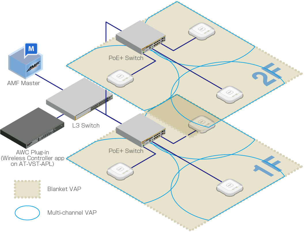
Here we assume the following configuration:
- There are two floors (1F and 2F).
- On both floors, we will operate wireless networks for employee PCs and mobile devices.
- On the first floor, we will also operate a separate wireless network for guests.
| Device Name | Node Name | IP Address | MAC Address | Role | |
|---|---|---|---|---|---|
| AMF Master | AT-VAA | AMF Cloud | |||
| Wireless Controller application container | AWC Plug-in | ||||
| AlliedWare Plus Layer 3 Switch | 192.168.1.1 | DHCP/NTP Server | |||
| 1F | PoE+ AlliedWare Plus Switch | x230-1F | Supplying power with PoE+ | ||
| TQ5403 | TQ5403-1F-1 | 192.168.1.100 | 00:00:5E:00:53:00 | AMF Guest Device | |
| TQ5403-1F-2 | 192.168.1.101 | 00:00:5E:00:53:20 | |||
| TQ5403-1F-3 | 192.168.1.102 | 00:00:5E:00:53:40 | |||
| 2F | PoE+ AlliedWare Plus Switch | x230-2F | Supplying power with PoE+ | ||
| TQ5403 | TQ5403-2F-1 | 192.168.1.103 | 00:00:5E:00:53:60 | AMF Guest Device | |
| TQ5403-2F-2 | 192.168.1.104 | 00:00:5E:00:53:80 | |||
| TQ5403-2F-3 | 192.168.1.105 | 00:00:5E:00:53:A0 |
- The AMF network has been added to the management database of Vista Manager EX.
- The PoE+ switch has been properly configured to accommodate APs as guest devices.
- The L3 switch has been configured with three VLANs, vlan1 (192.168.1.0/24) as the default VLAN and vlan100 (192.168.100.0/24) and vlan200 (192.168.200.0/24) for wireless clients. A DHCP pool for each VLAN has also been set up.
- The PoE+ switch ports for the wireless APs (and other required ports) have been configured with vlan1 as the native VLAN and vlan100, vlan101, vlan200 and vlan201 as the tagged VLANs for normal traffic.
- APs will get their IP addresses from the DHCP server running on the L3 switch.
- AMF devices have been set up to accommodate wireless APs as guest devices.
- PoE+ switches have been configured to collect the guest device information automatically ("discovery dynamic").
- PoE+ switches have been configured to perform DHCP Snooping on the AP management VLAN (vlan1).
Configure External IP Address for AWC Plug-in
When using the AWC Plug-in on VST-APL to manage wireless APs, it is recommended to register the IP address of the Wireless Controller application (AWC Plug-in) on the VST-APL as an external IP address in the System Setting screen of the AWC Plug-in in advance.If you have already configured the external IP address of the AWC plug-in correctly, this step is not necessary.
- Click on System Setting from the AWC Plug-in menu.
The "System Setting" screen appears.
- In "External IP Address for AWC plug-in" under "IP Address Settings", select the IP address of the Wireless Controller application (i.e., AWC Plug-in) on the VST-APL from the dropdown list.
- Click on the "Save" button on the right side of "IP Address Settings".
09 Sep 2021 17:37