Manually Adding Devices
This section explains how to register (add) devices manually. This is the most fundamental operation for using AMF Security mini.
To manually add a device into AMF Security mini's database, you have to know the interface MAC address of the device.
Registering AMF Members
When registering an AMF master on the AMF > AMF Application Proxy Settings page, the status of AMF members connected to AMF Security mini can be checked on the Switches > Active AMF Member List page.- Open the Switches > Active AMF Member List page.
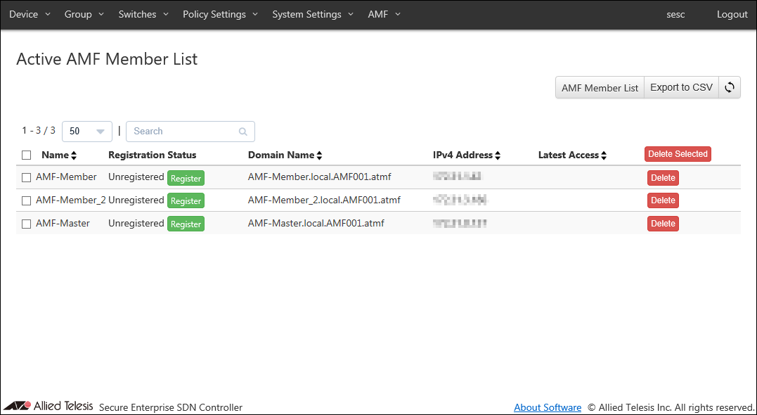
- Before registration, Register Status column shows a string "Unregistered" and you can see the "Register" button next to it. To register an AMF Member, click the "Register" button to open the Switches > AMF Member Add page.
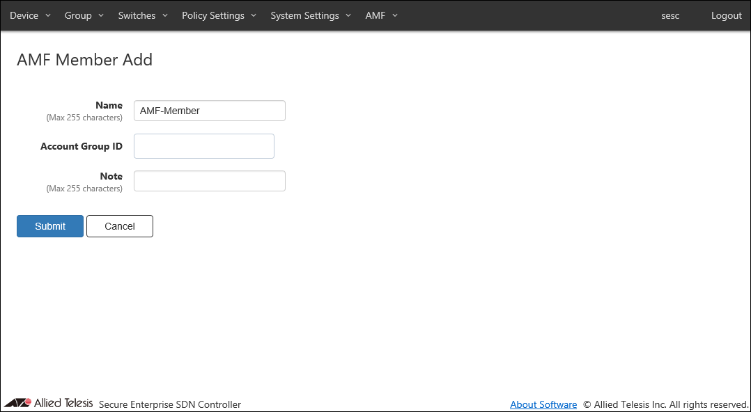
- Enter something in Note.
As an example, configure the settings shown in the following table: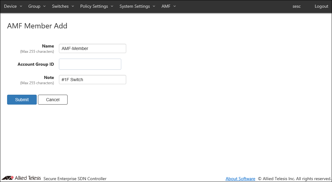
Table 1: Sample Configuration Data
Item Name Value Description Name (Mandatory) AMF-Member (Not Changed) Name of the AMF Member.
The Name cannot be the one already used in the Switches > AMF Member List page.
Max 255 characters. Can use alphanumeric, hyphen (-) and underscore (_).Note #1F Switch Arbitrary string (comment) for the AMF Member.
Max 255 characters.Note
Name must be the same as the host name of AMF Member. This is because AMF Member is managed by the host name of AMF Member.
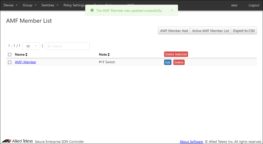
- Click the "Submit" button.
Once the AMF Member is registered, the Switches > AMF Member List page reflects the newly added information.
Registering Guest Network
Networks can be added on the Policy Settings > Add Network page.- Open the Policy Settings > Network List page.
This page shows the list of networks registered in AMF Security mini's database. As you see, no network is registered yet.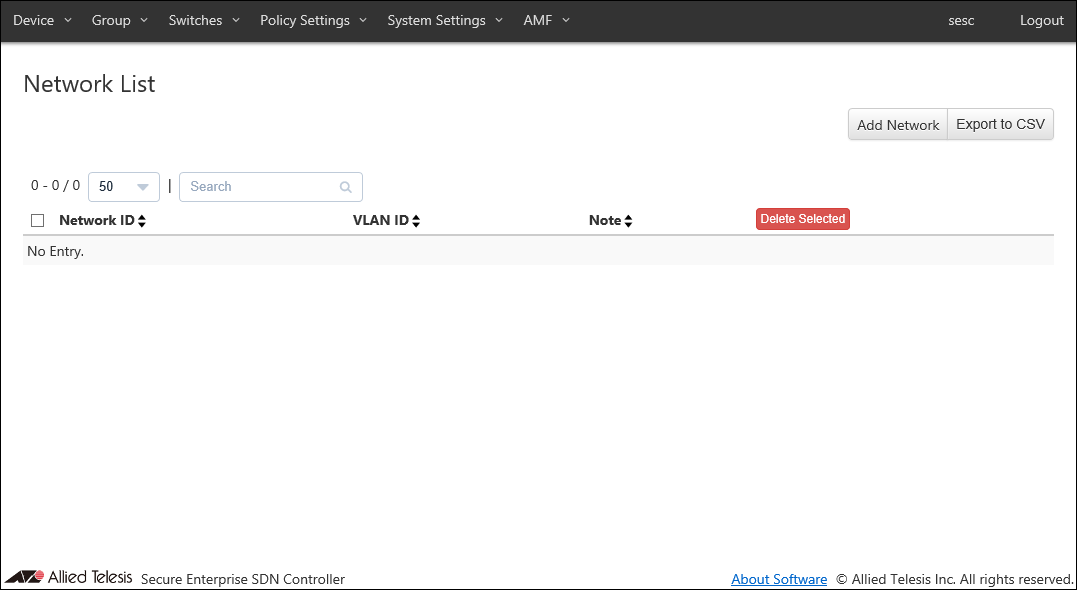
- Click the "Add Network" button at the top right corner to move to the Policy Settings > Add Network page.
This page lets you specify a network ID (network name) and a VLAN ID for the network.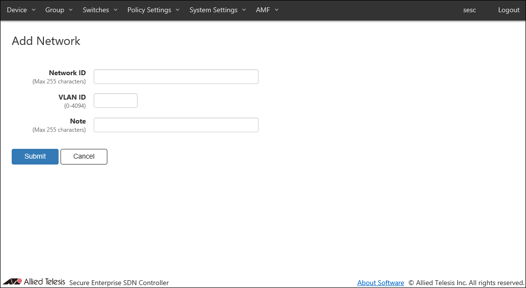
By setting the connection destination network, you can control the VLAN segment to which the connection permitted device is connected. AMF Security mini achieves this by telling switches to add appropriate VLAN tags to the packet originating from the allowed devices.
- Enter information for the network to add.
As an example of registering the network "Sales", configure the settings shown in the following table: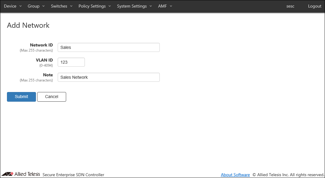
Table 2: Sample Configuration Data
Item Name Value Description Network ID (Mandatory) Sales ID (Name) of the network.
Network ID must be unique.
Max 255 charactersVLAN ID (Mandatory) 123 A VLAN ID for the network. You cannot specify a VLAN ID which is already assigned to another network.
If you specify VLAN ID 0, VLAN tag is not added for the network. This is the same as the network is not specified in a policy.
VLAN ID must be in the range of 0 to 4094.Note Sales Network Arbitrary string (comment) for the network.
Max 255 characters.
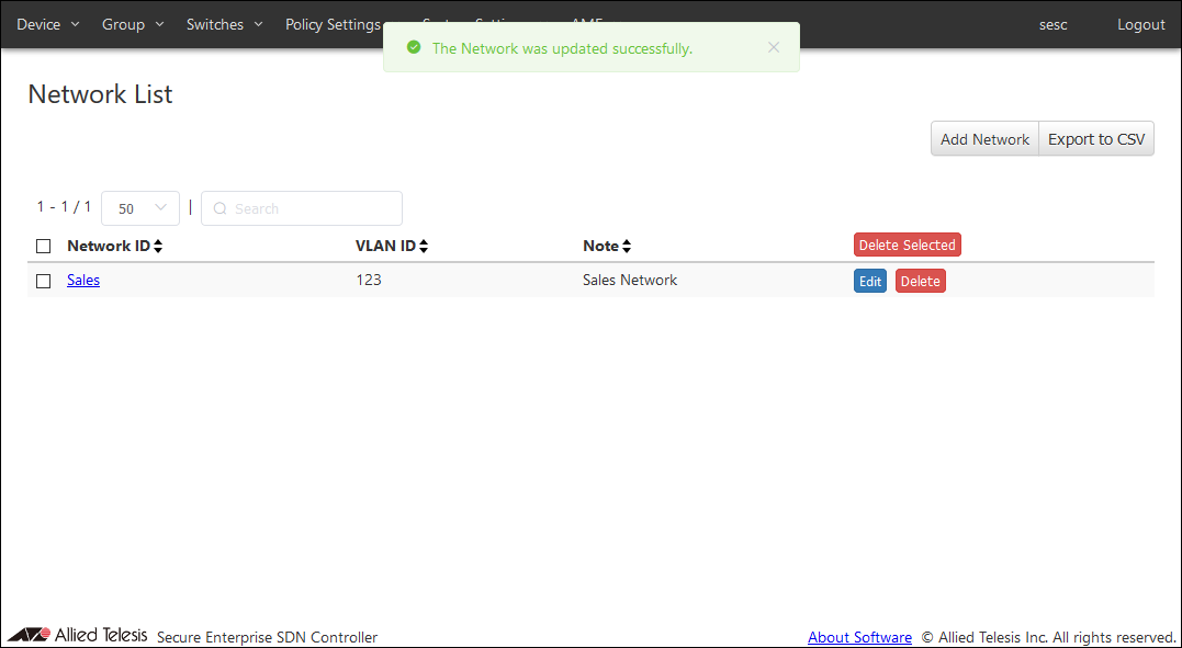
- Click the "Submit" button.
Once the network is registered, the Policy Settings > Network List page reflects the newly added information.
Registering Location
In AMF Security mini, a physical location from where a device can access the network is called Location.Location can be added on the Policy Settings > Add Location page.
- Open the Policy Settings > Location List page.
This page lists registered locations in AMF Security mini. As you see, no location is registered at this point.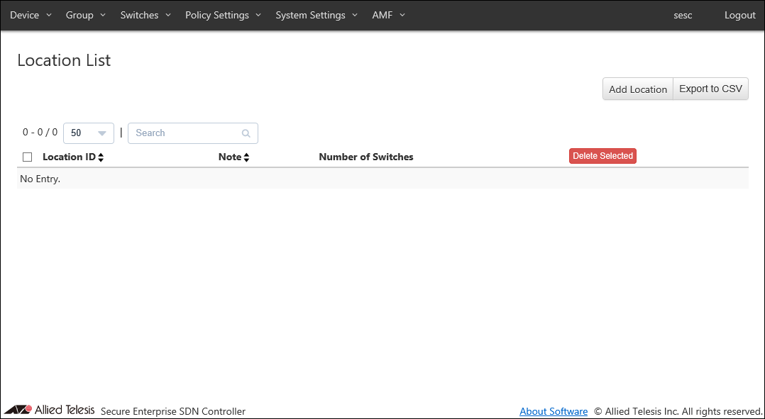
- Click the "Add Location" button at the top right corner of the Policy Settings > Location List page to move to the Policy Settings > Add Location page.
A location consists of a Location ID (its name) and a list of the AMF Members which are installed in the location.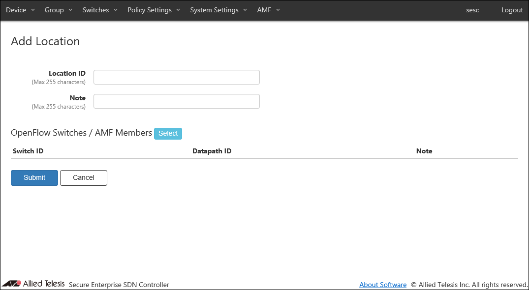
Using locations, you can control the AMF Members to which a device can connect by location such as an office floor or a meeting room.
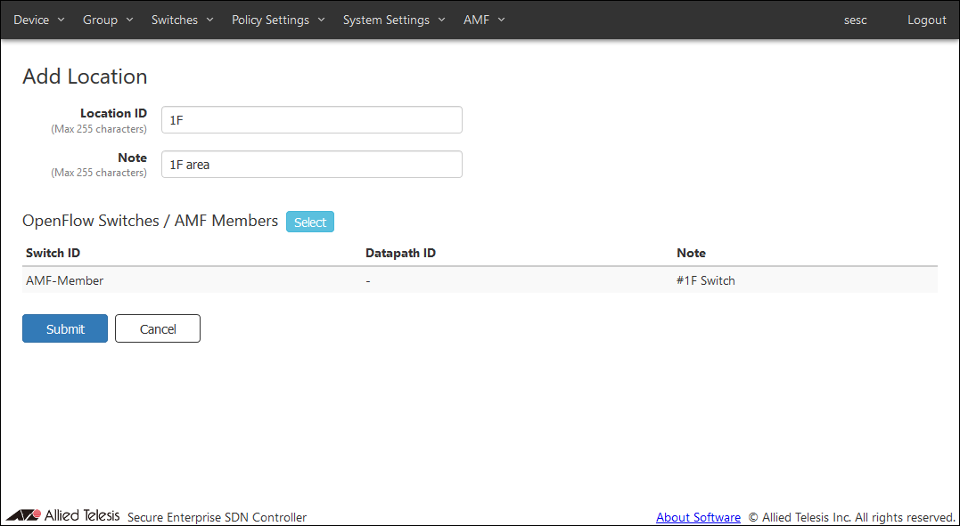
- Enter information about the new location.
As an example of registering the location "1F", configure the settings shown in the following table: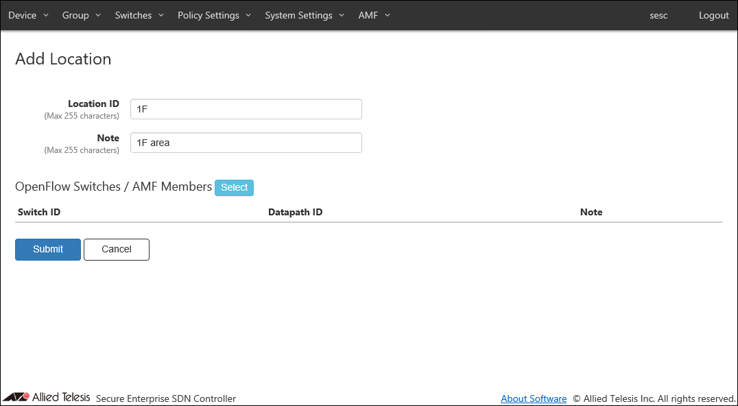
Table 3: Sample Configuration Data
Item Name Value Description Location ID (Mandatory) 1F ID (Name) of the location.
Location ID must be unique.
Max 255 charactersNote 1F area Arbitrary string (comment) for the location.
Max 255 characters.
- Click the "Select" button next to "OpenFlow Switches / AMF Members".
The Policy Settings > OpenFlow Switches / AMF Members dialog appears and shows the AMF Members which have been added in "Adding AMF Member".
Assuming that the already registered "AMF-Member" is installed at the physical location "1F", check the check box at the left end of the "AMF-Member" line.
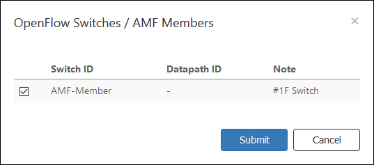
- Click the "Submit" button.
In the Policy Settings > Add Location page, the selected "AMF-Member" is displayed in the "OpenFlow switches / AMF members".
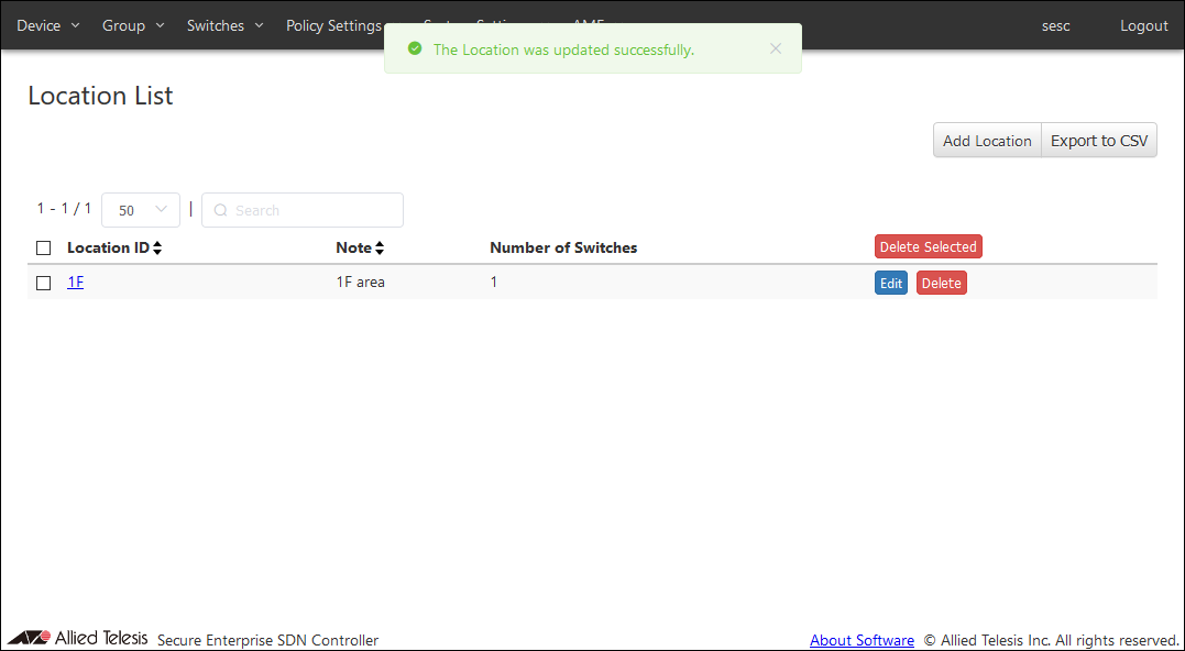
- Click the "Submit" button.
Once the location was added, the Policy Settings > Location List page reflects the newly added information.
Registering Schedule
A schedule can be added on the Policy Settings > Add Schedule page.- Open the Policy Settings > Schedule List page.
This page shows the list of schedules. As you see, there is no schedule at this point.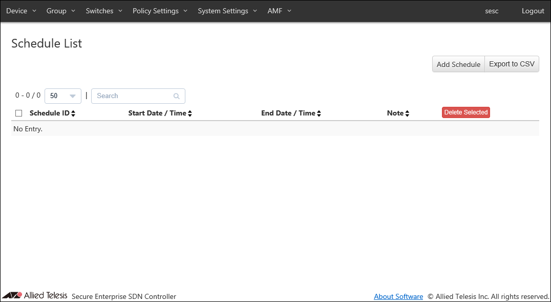
- Click the "Add Schedule" button at the top right corner of the Policy Settings > Schedule List page to move to the Policy Settings > Add Schedule page.
By adding schedules, you can control when a device can connect to the network. If one of the Start Date / Time or the End Date / Time is not specified in a schedule, AMF Security mini treats it as if it has no time limitation.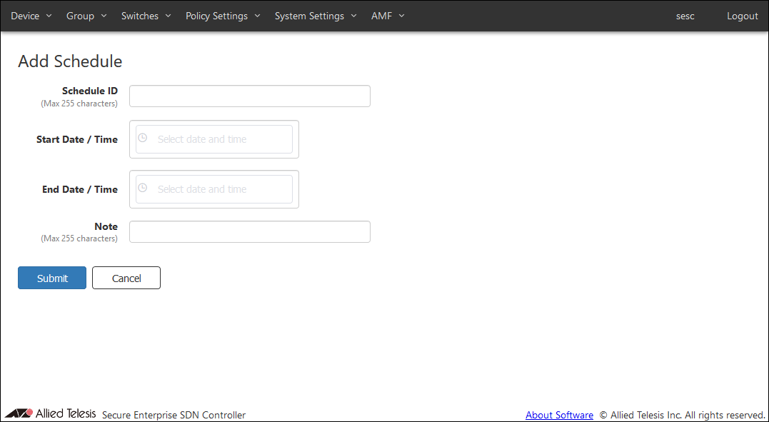
- Enter information about the new schedule.
As an example of registering the schedule "March Events", configure the settings shown in the following table: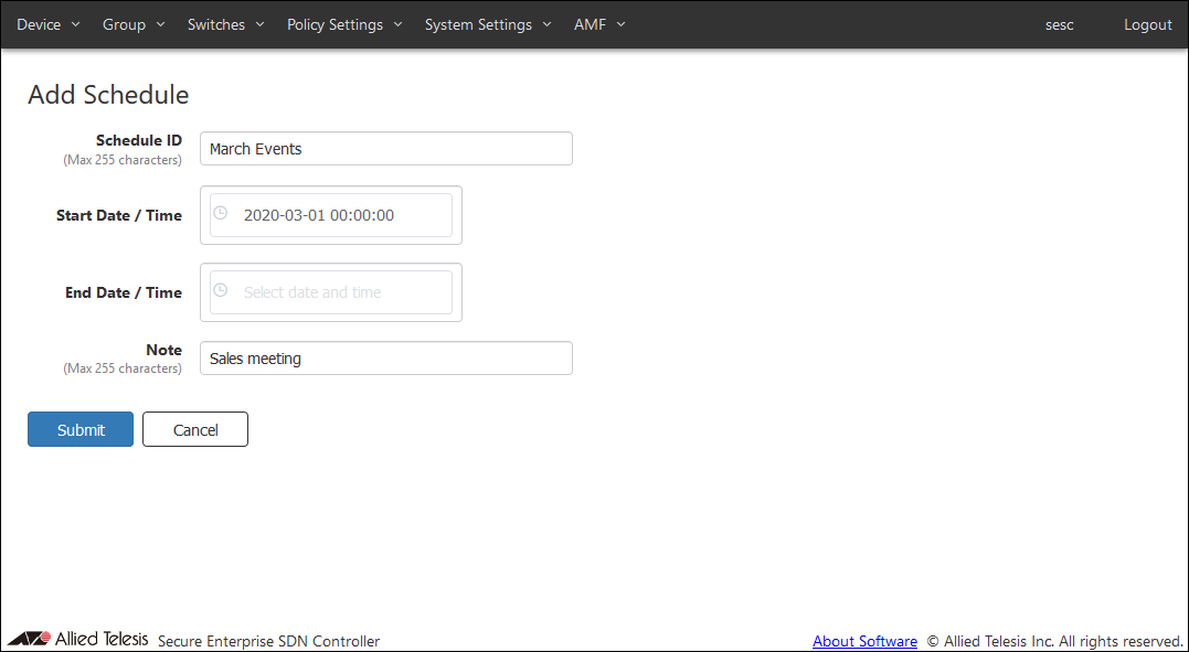
When the End Date / Time is not specified, this schedule is effective indefinitely after the Start Date / Time.Table 4: Sample Configuration Data
Item Name Value Description Schedule ID (Mandatory) March Events ID (Name) of the schedule.
Schedule ID must be unique.
Max 255 charactersStart Date / Time 2020-03-01 00:00:00 The beginning of the time range when a device is allowed to connect to the network.
Date / Time can be selected using calendar controls or entered manually. When you enter them manually, use the format "YYYY-mm-dd" for date and "HH:MM:SS" for time.End Date / Time (empty) The end of the time range when a device is allowed to connect to the network.
Date / Time can be selected using calendar controls or entered manually. When you enter them manually, use the format "YYYY-mm-dd" for date and "HH:MM:SS" for time.Note Sales meeting Arbitrary string (comment) for the schedule. Max 255 characters.
- Click the "Submit" button.
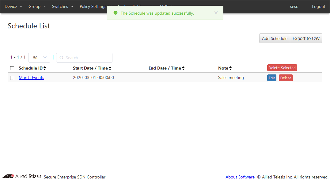
Once the schedule was added, the Policy Settings > Schedule List page reflects the newly added information.
Registering Device
AMF Security mini can control access to the network by registered devices.Devices can be added on the Device > Add Device page.
NoteA device which is not attached any security policy is temporarily assigned to the untagged VLAN. When you are going to add the device which has already been used by its user, Allied Telesis recommends you to take the following steps so that you can perform the whole process from adding the device to applying a security policy to it in a batch.
- Open the Device > Device List page.
This page shows the list of devices registered in AMF Security mini's database. As you see, no device is registered at this point.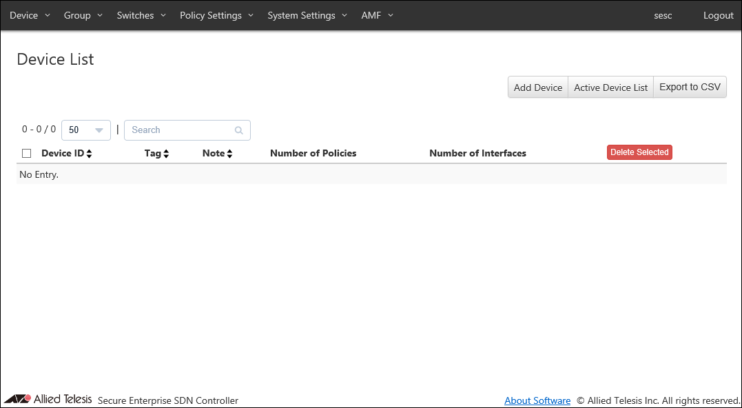
- Click the "Add Device" button at the top right corner of the Device > Device List page to move to the Device > Add Device page.
This page lets you enter an ID for the device, plus a tag and a note if required.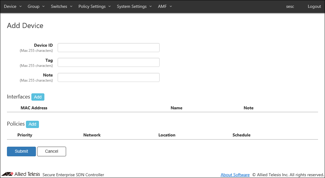
- Enter information about the new device.
As an example, configure the settings shown in the following table: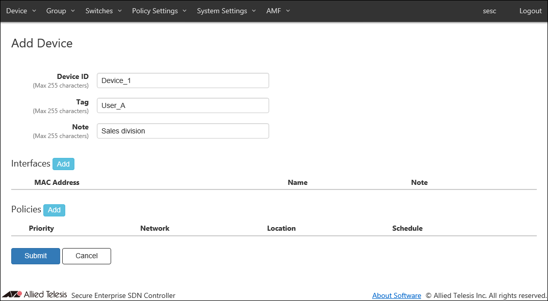
Table 5: Sample Configuration Data
Item Name Value Description Device ID (Mandatory) Device_1 ID (Name) of the device to register.
Device ID must be unique.
Max 255 charactersTag User_A Secondary name of the device which can be used by administrators to easily distinguish, categorize or filter devices.
Max 255 charactersNote Sales division Arbitrary string (comment) for the device.
Max 255 characters.
- Next, you have to enter the interface MAC address of the device. AMF Security mini denies all network connections from unregistered MAC addresses.
Click the "Add" button next to "Interfaces" to open the Device > Edit Interface dialog.
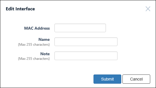
Note
You can temporarily allow unregistered devices to access the network in a specific VLAN segment. In this case, it is necessary to separately set the UnAuth Group on the Group > Add UnAuth Group page.
- Enter the MAC address of an interface of the device. You can optionally input a name and a note for the interface too.
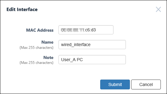
- Click the "Submit" button.
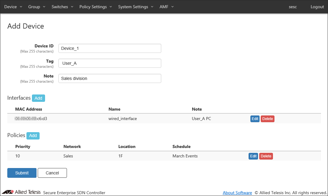
The MAC address of the configured interface is displayed in the "Interface" list on the Device > Add Device page.
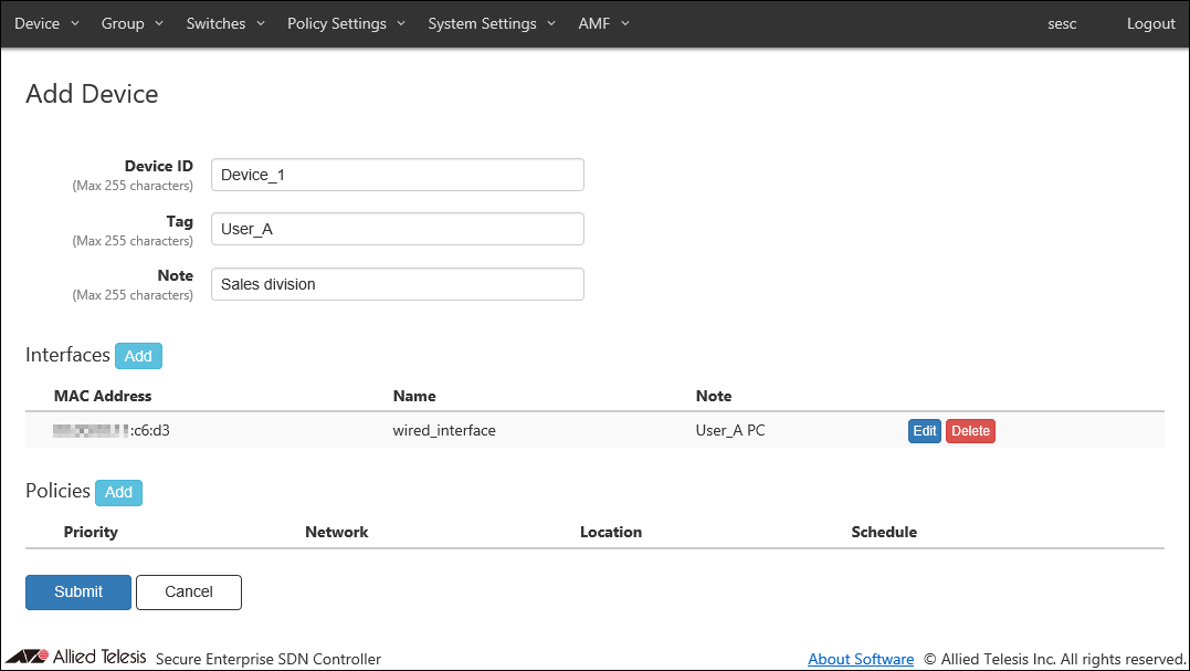
- Next, you have to apply a security policy to the device.
Click the "Add" button next to "Policies" to open the Device > Edit Policy dialog.
To each device, you can apply a security policy which defines from where and when the device can connect to the network.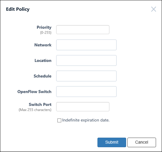
A device which is not applied any security policy can connect to the untagged VLAN network anytime and from anywhere.
Note
If the VLAN set in the AMF Member is accessible, the device may be able to connect to the equipment on the control plane depending on the switch settings.
- Enter the policy's priority in the range of 0 to 255.
When a device has multiple security policies attached, AMF Security mini searches for a matching policy from the one with the lowest priority value to the highest.
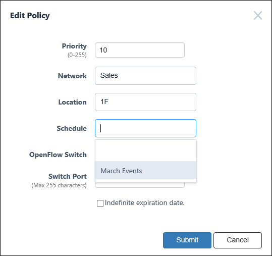
In this example, the security policy priority is set to 10.
- The registered information is listed in the drop-down lists of "Network", "Location", and "Schedule". You can choose the elements from the drop-down list for the device.
The drop-down list can contain maximum 100 elements at a time. If you enter text in the field, elements in the drop-down list are dynamically filtered to the ones which contain the input text (it shows maximum 100 elements). From the drop-down list, select a policy element to apply to the device.
With the following policy settings, the device can access the network "Sales" from the location "1F" during the time period specified by the schedule "March Events".
In this example, there is only one element each for the Network, Location and Schedule. So you do not have to filter elements. Just click the element in each of the drop-down list.
- Click the "Submit" button.
"Policies" section of the Device > Device List page shows the security policy which you just added.
- Click the "Submit" button.
Once the device is added, the Device > Device List page reflects the updated information.
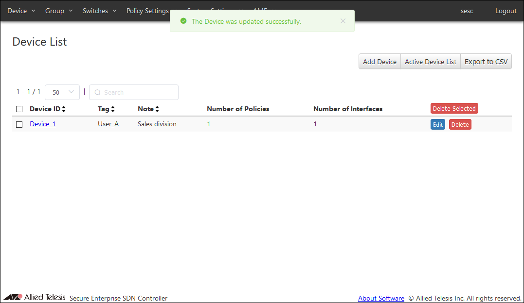
You are done with the basic configurations.
18 Jan 2021 10:56