Controlling Devices with TQ's AMF Application Proxy
Setting example of TQ's AMF Application Proxy
The following is an example of setting TQ's AMF Application Proxy.This example is a basic setting for TQ's AMF Application Proxy Whitelist and TQ's AMF Application Proxy Blacklist.
The application linked by AMF Application Proxy Blacklist uses the UTM-related function of the AT-AR3050S / AR4050S of the AR router, and the action is set to Quarantine (assign to the specified VLAN).
In this setting example, when TQ dynamic VLAN is disabled, it is taken as an example. The differences in the settings when TQ dynamic VLAN is enabled are explained in Note.
In addition, enable critical mode so that the wireless terminal to be newly connected when a failure such as a power failure occurs in AMF Security belongs to the VLAN ID set in the VAP.
NoteFor TQ's AMF Application Proxy, when WPA Enterprise is selected for security in the VAP (multi-SSID) setting, the operation at the time of authentication differs depending on whether the dynamic VLAN is disabled or enabled. For details, refer to What is AMF Security > TQ's AMF Application Proxy/Behavior when using TQ dynamic VLAN.
For the operation of critical mode, refer to What is AMF Security > TQ's AMF Application Proxy/Critical mode.
◼ Setting flow
Make the settings when using TQ's AMF Application Proxy according to the following flow.
- Set AMF Security IP Address in AWC Plug-in system settings
- Set AMF Application Proxy Server (AMF Security) information in the AP common settings / VAP (multi-SSID) settings of the AWC Plug-in.
- Apply AP common settings to TQ with AWC Plug-in
- Set Vista Manager EX and TQ information in AMF Security
- Set rules for UTM-related functions of AT-AR3050S / AR4050S used as an application linked to AMF Security
- Set authentication data for AMF Application Proxy Whitelistin AMF Security (policy, device)
- Setting to send threat information detected by UTM related functions to AR router to AMF Security by syslog message
NoteAMF Application Proxy to be set in TQ can be set from AWC Plug-in.
◼ Configuration
The following configuration is assumed in this setting example, but it is assumed that the basic settings for each product have been completed.
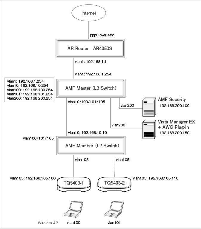
◼ Main basic settings
- AR router AR4050S
PPPoE Internet connection + firewall / UTM
- Vista Manager EX & AWC Plug-in
AMF network settings, wireless AP registration (created AP common settings have been applied to TQ)
- AMF Security
Network Settings (IP Address setting)
- Switches
AMF Master (L3 switch), AMF Member (L2 switch), VLAN for wireless terminal communication
NoteAMF Security and Vista Manager EX / TQ / AR router enable IPv4 communication regardless of the same segment or different segments.For details on the settings of each product, refer to the documentation of each product.
◼ Information on each product
The information for each product is shown below.
| IP Address | 192.168.200.150 |
| User ID | manager |
| Password | TopSecret0! |
| AWC Plug-in Port Number | 5443 |
| IP Address | 192.168.200.100 |
| Source IPv4 Address when sending syslog messages | IP Address of vlan1 interface (192.168.1.1) |
◼ Setting information for each product
The information to be set for each product is shown below.
| Item Name | Value |
|---|---|
| System Settings / Permissions Settings / AMF Security Web API | |
| AMF Security IP Address | 192.168.200.100 |
| Wireless Settings / AP Common Settings / VAP (multi-SSID) Settings / Detailed Settings | |
| MAC Access Control | AMF Application Proxy |
| AMF Application Proxy Server Primary IP Address | 192.168.200.100 |
| AMF Application Proxy Server Primary Secret | password |
| AMF Application Proxy Server Port Number | 1812 |
| Critical mode | Enabled |
NoteAMF Application Proxy Server Port Number is only supported for 1812.
| Item Name | Value |
|---|---|
| AMF / TQ Settings | |
| Common Settings | |
| Quarantine VLAN ID | 250 |
| VistaManagerEX | |
| Vista Manager EX IPv4 Address | 192.168.200.150 |
| AWC Plug-in Port Number | 5443 |
| Vista Manager EX User Name | manager |
| Vista Manager EX Password | TopSecret0! |
| TQ | |
| TQ5403-1 IPv4 Address | 192.168.105.100 |
| Pre-Shared Key | password |
| TQ5403-2 IPv4 Address | 192.168.105.110 |
| Pre-Shared Key | password |
| System Settings / Trap Monitor Settings / Rules | |
| Host Addresses | 192.168.1.1 |
| OpenFlow/TQ Action | Quarantine |
| Trap Action Target List | Check all |
| Item Name | Value |
|---|---|
| Device1 | |
| Device ID | Device1 |
| MAC Address | 00:00:00:00:00:01 |
| Network (VLAN) | VLAN100 |
| Device2 | |
| Device ID | Device2 |
| MAC Address | 00:00:00:00:00:02 |
| Network (VLAN) | VLAN101 |
| Item Name | Value |
|---|---|
| Log output destination of UTM related functions | 192.168.200.100 |
Configuring AWC Plug-in
- Set the AMF Security IP Address to allow access.
From the AWC Plug-in menu, click the "Edit" button in "System Settings" → "Permission Settings".
The Access Permission Settings (AMF Security WebAPI) dialog is displayed.
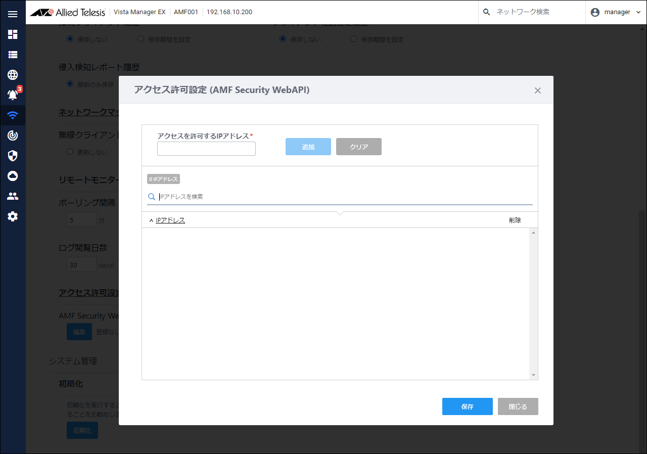
- Enter the AMF Security IP Address "192.168.200.100" as the IP Address to allow access, and click the "Add" button.

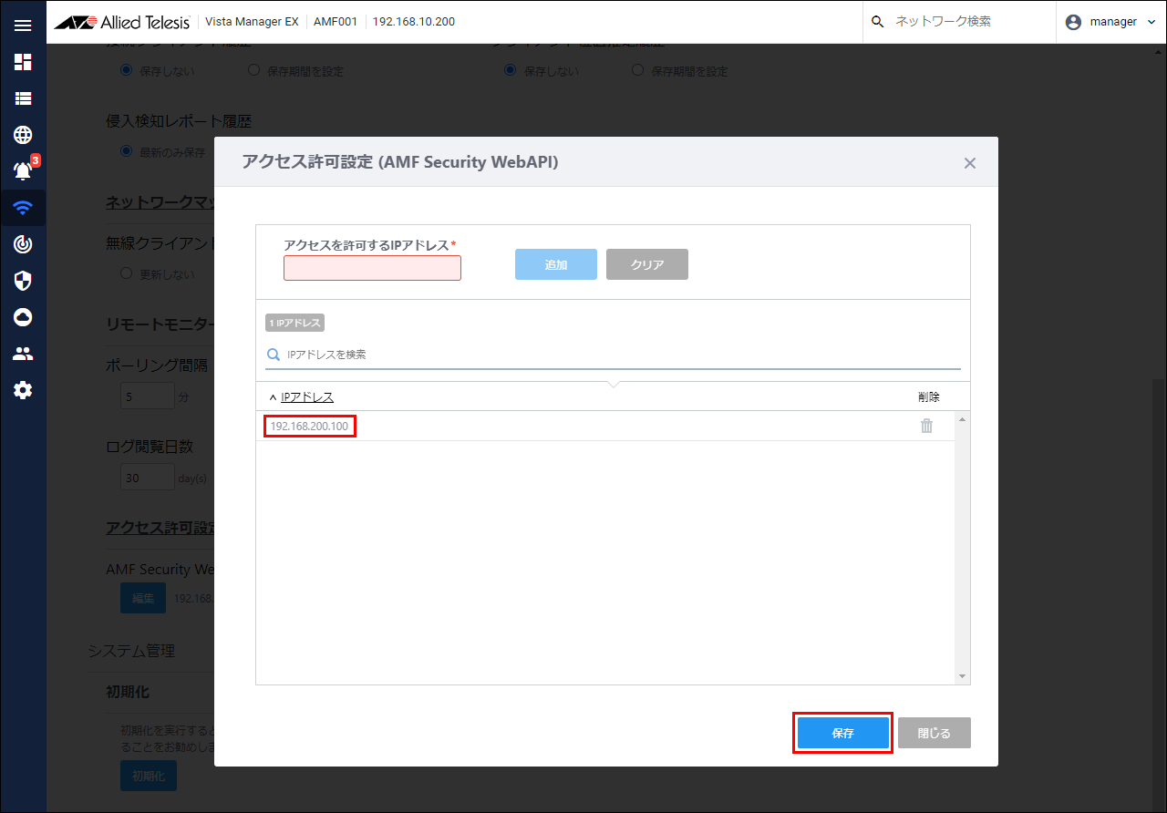
- Confirm that the IP Address "192.168.200.100" entered in the IP Address field is displayed, and click the "Save" button.
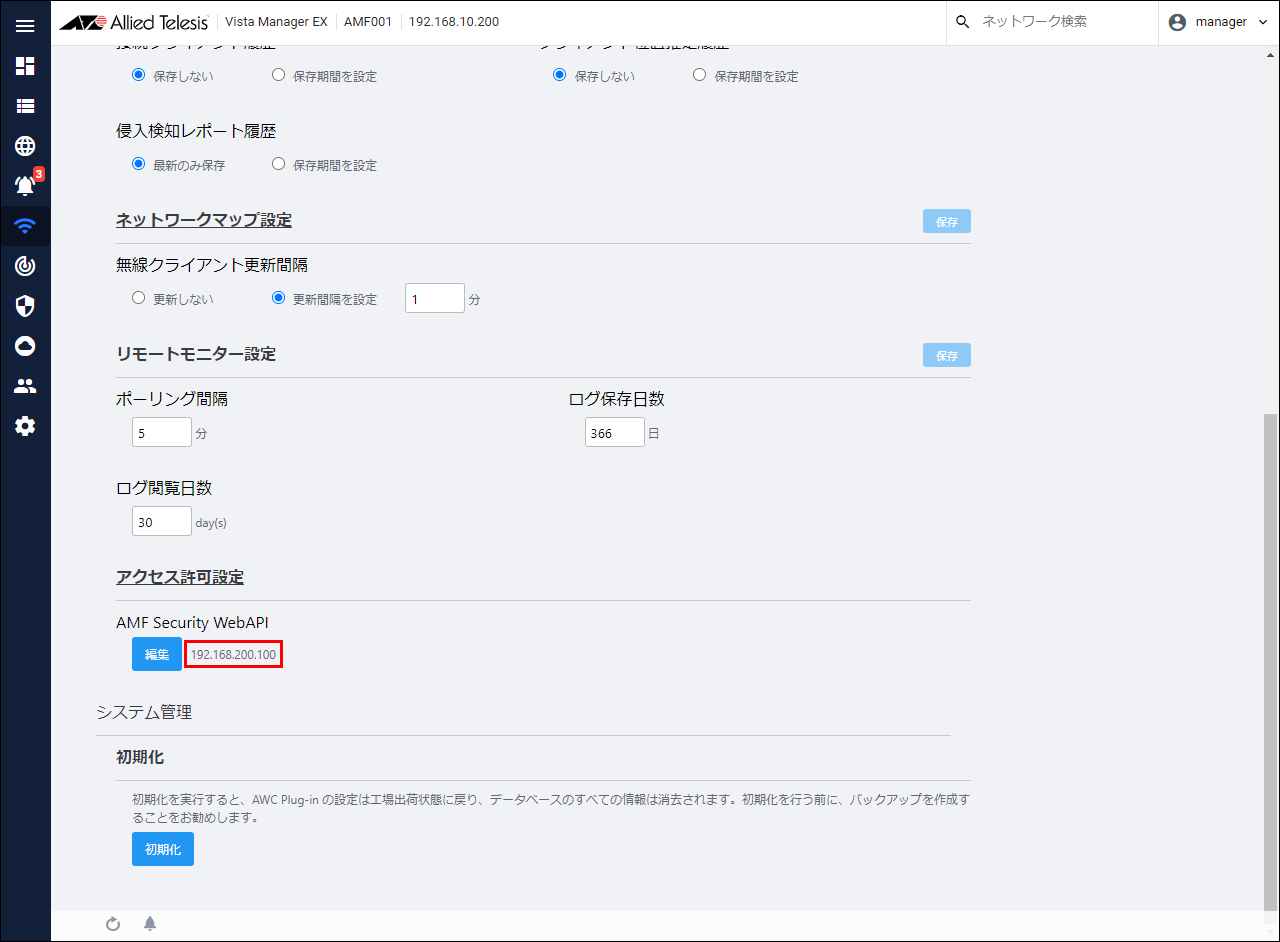
- Confirm that the set IP Address "192.168.200.100" is displayed next to the "Edit" button in "Access Permission Settings".
- Set AMF Application Proxy information in the AP Common Settings assigned to TQ.
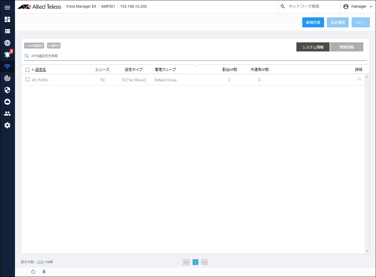
From the AWC Plug-in menu, click "Wireless Settings" → "AP Common Settings".
The AP Common Setting list is displayed.
Note
AMF Application Proxy sets the VAP. Therefore, configure all VAPs that use AMF Application Proxy.
- From the AP Common Settings list, click the "Details" button (worm glasses icon) of the AP Common Settings to be edited.
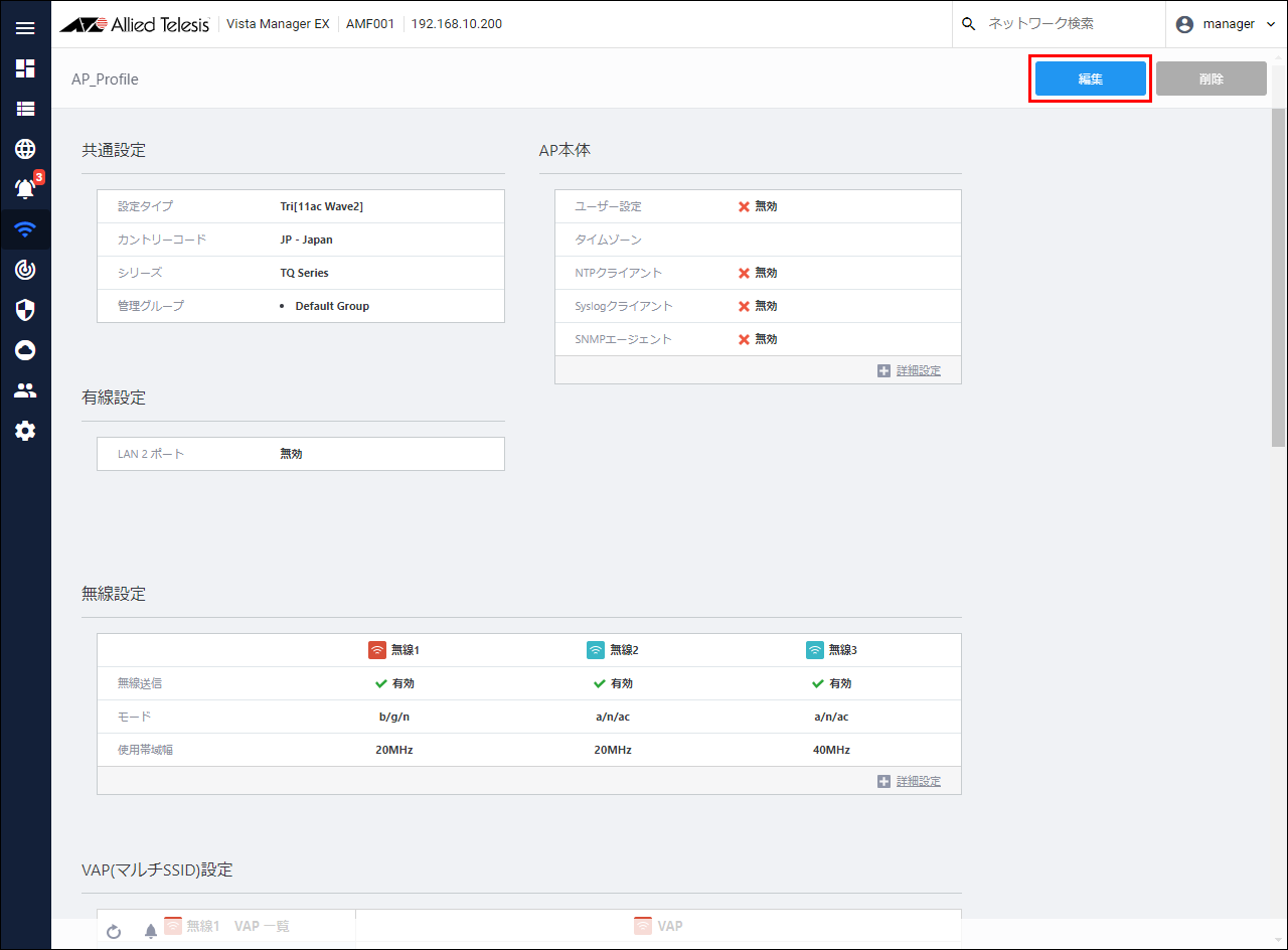
- The details page of AP Common Settings is displayed. Click the "Edit" button at the top right of the content field.
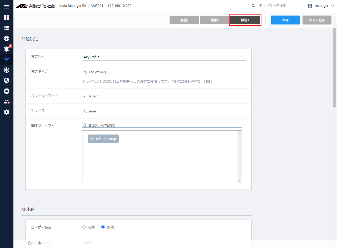
- Select the wireless band you want to set from the buttons at the top of the page.
Here, select Radio 3.
- Click the VAP you want to configure from the VAP list in the VAP (Multi-SSID) settings, and then click Detail.
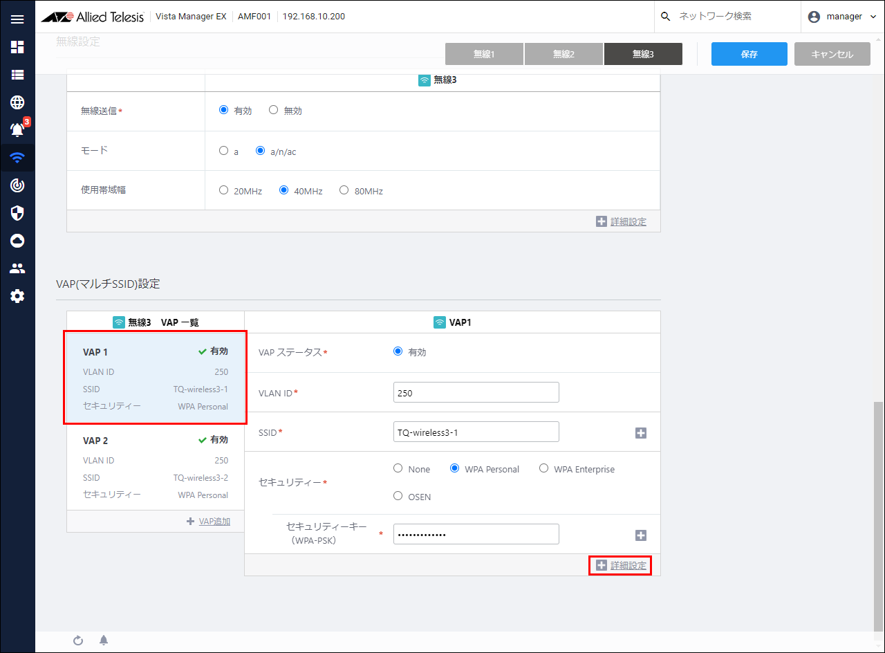
- Select "AMF Application Proxy" in MAC Access Control.
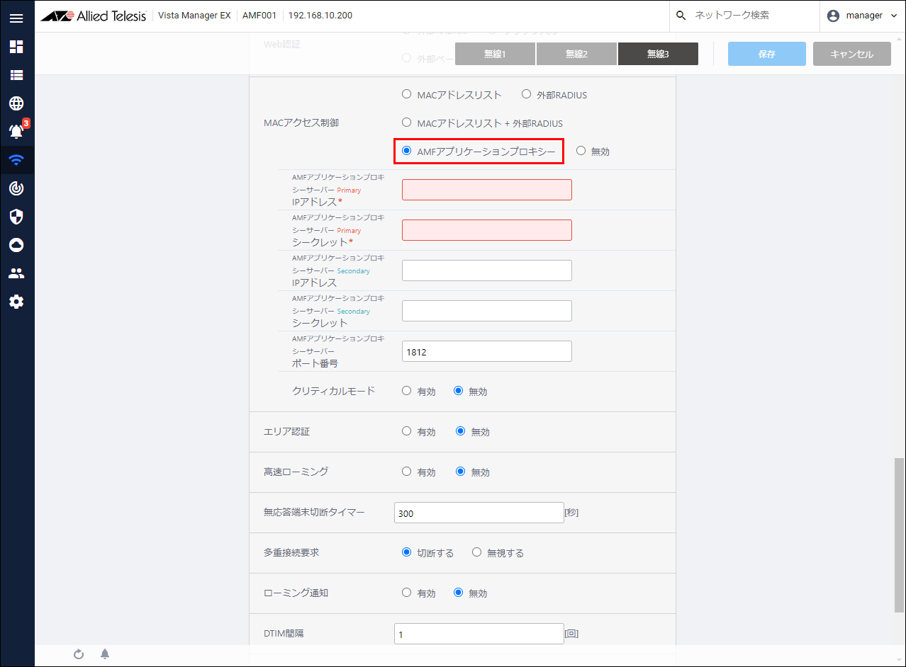
- Set AMF Application Proxy related information.
Set the following information.
Table 8: Configurable fields
Item Name Value AMF Application Proxy Server Primary IP Address 192.168.200.100 AMF Application Proxy Server Primary Secret password AMF Application Proxy Server Port Number 1812 Critical mode Enabled
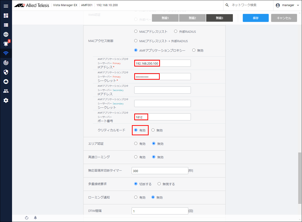
- After setting the above information, click the "Save" button at the top right of the content field.
Wait until the settings are reflected.
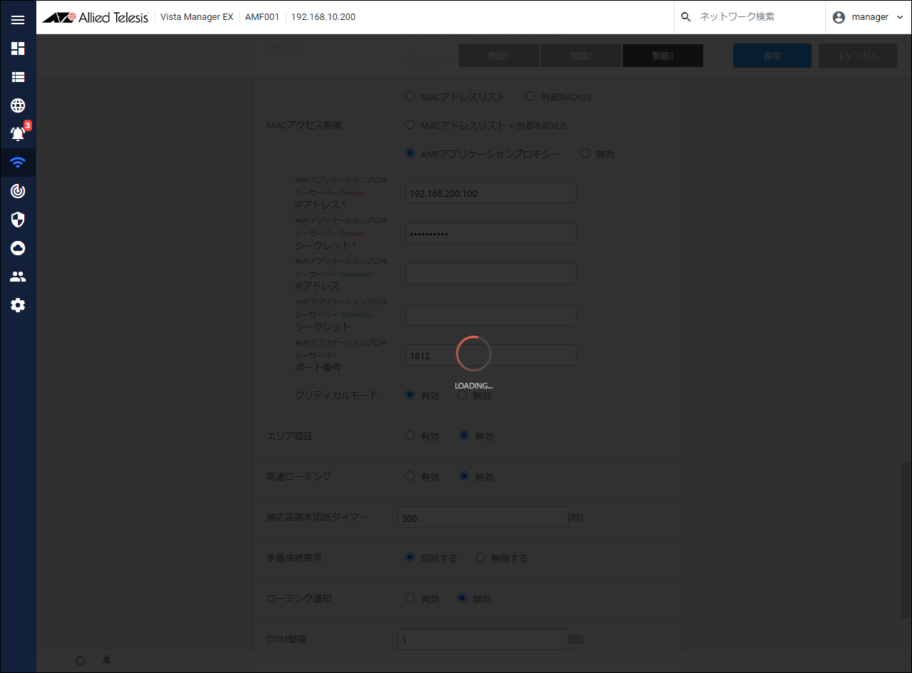
When the settings are reflected, the page returns to the details screen of AP Common Settings.
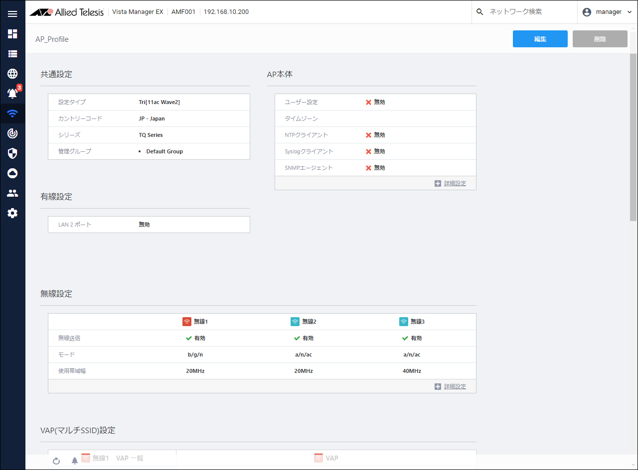
- Apply AP Common Settings to TQ.
From the AWC Plug-in menu, click "Wireless Settings" → "AP Registration / Settings".
A list of wireless APs is displayed.
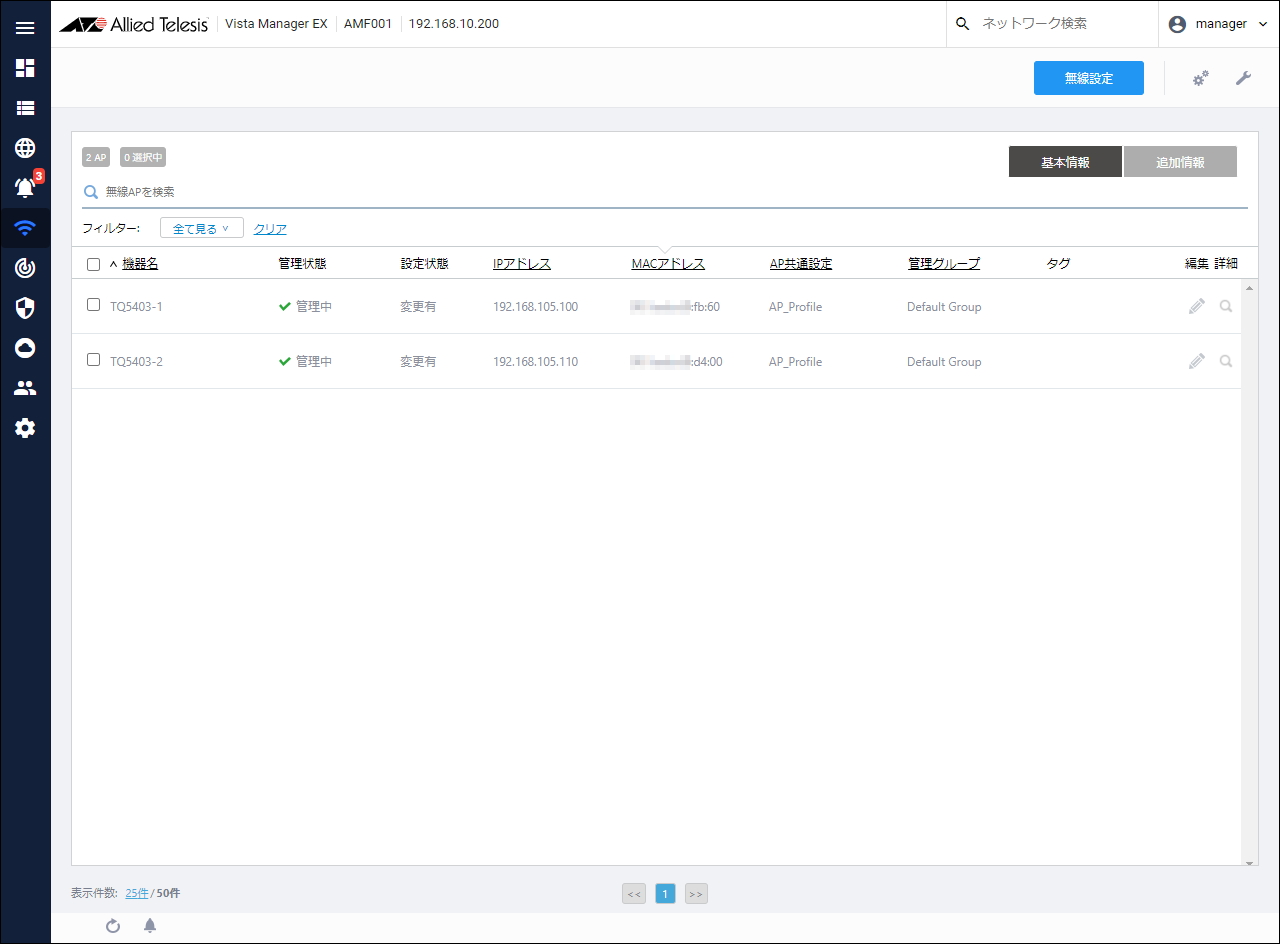
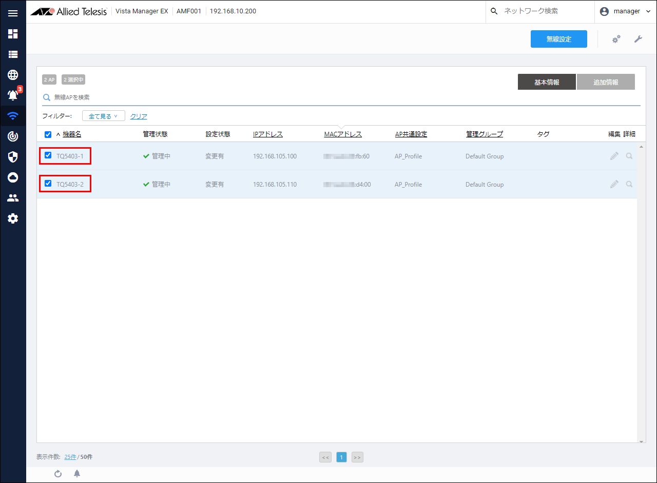
- Check the check boxes of the wireless APs "TQ5403-1" and "TQ5403-2".
- Mouse over the spanner icon at the top right of the content field and click "Apply Settings" from the menu that appears.
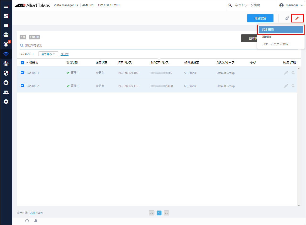
- The "Apply Settings" dialog will be displayed. Click the "OK" button.
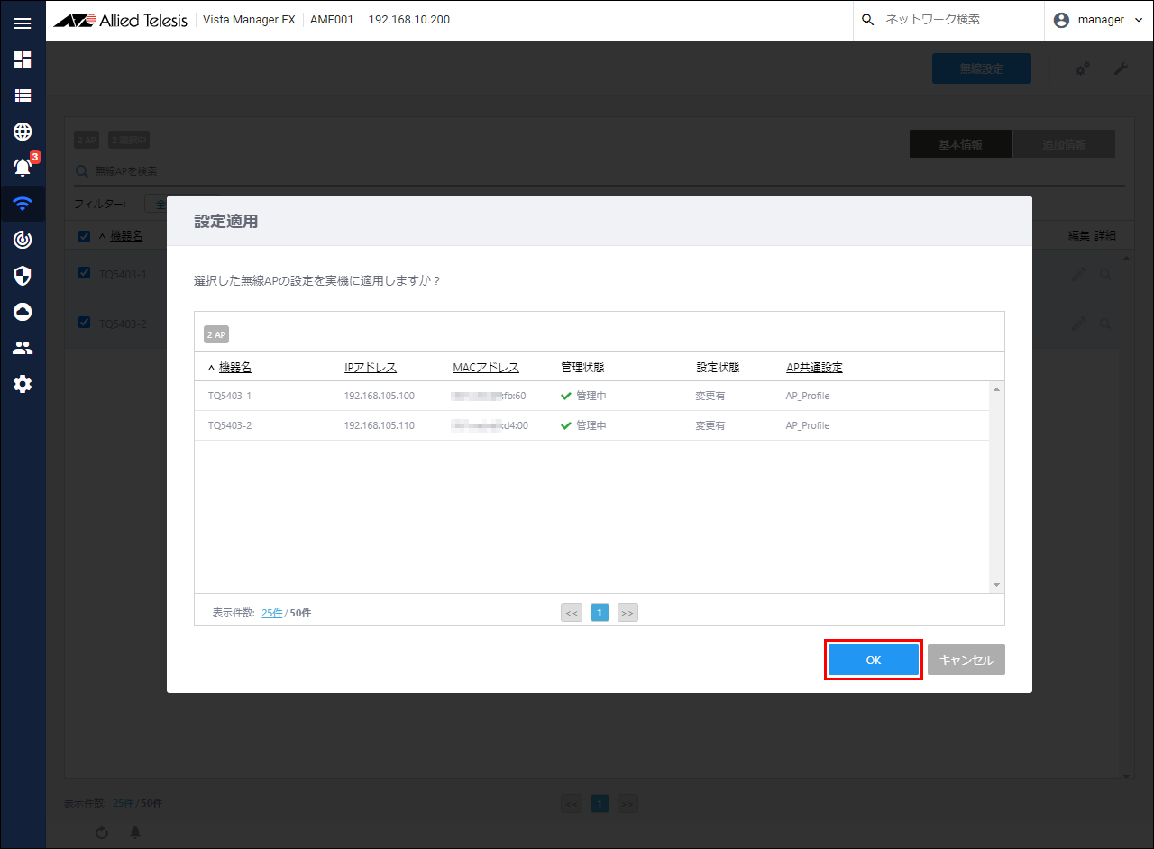
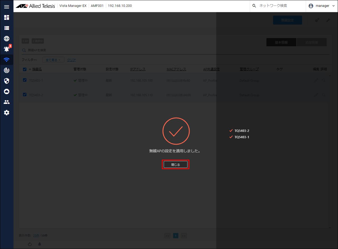
- When the completion message is displayed, click the "Close" button.

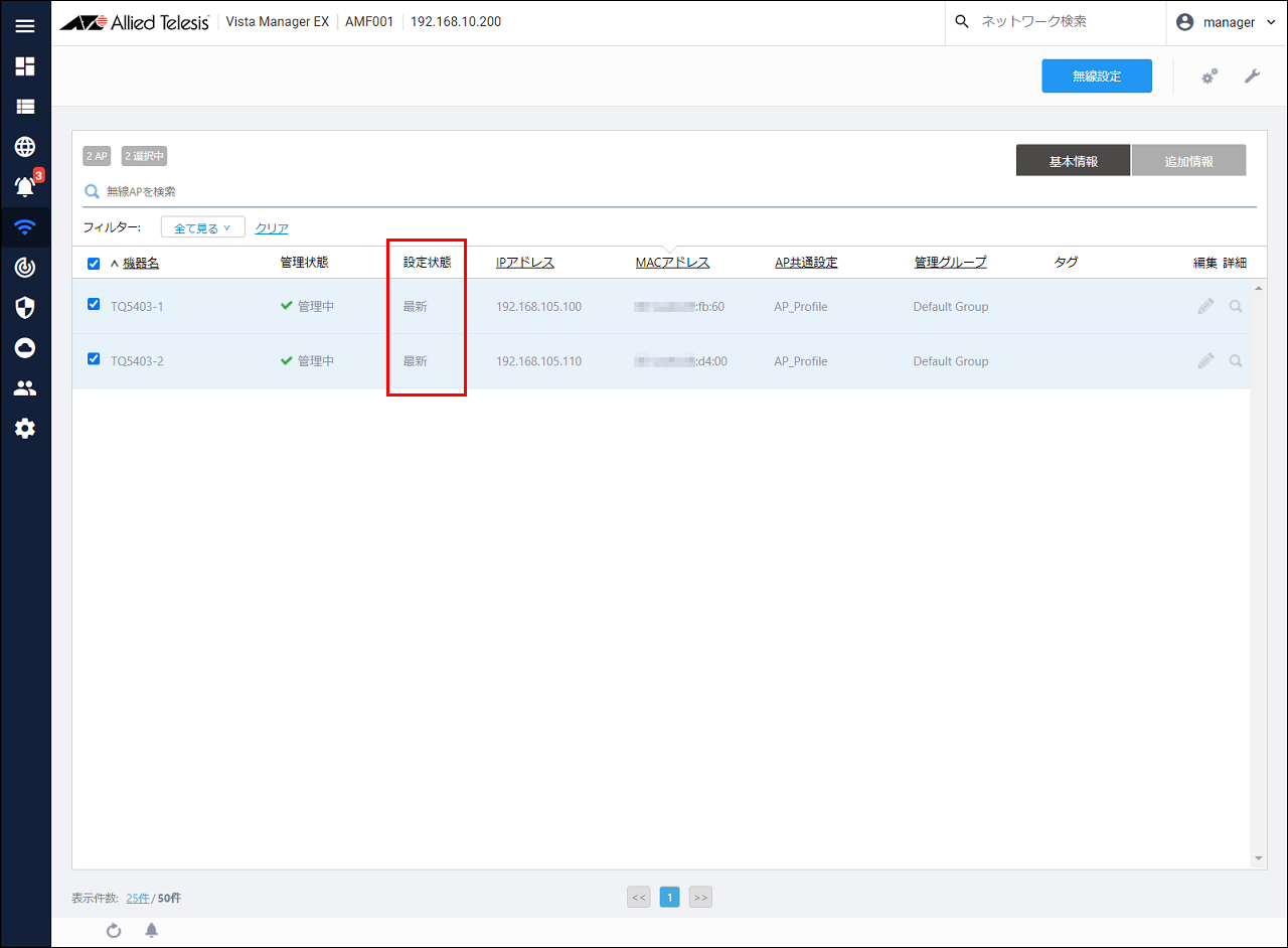
- Make sure that the "Setting status" is "Latest".
Configuring AMF Security
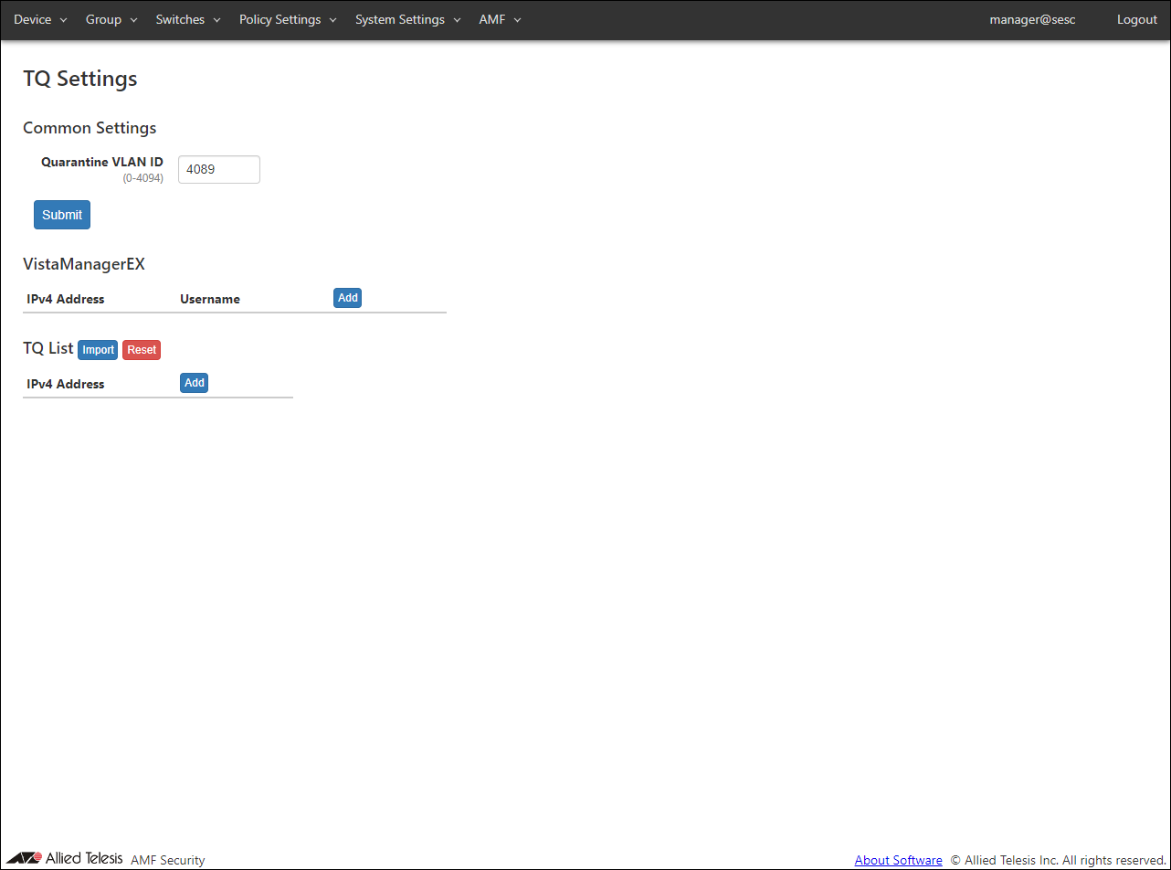
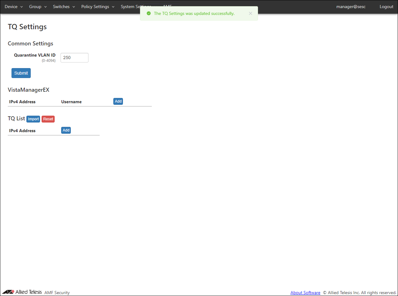
- Display the AMF > TQ Settings page and set the isolated VLAN ID, Vista Manager EX, and TQ information.
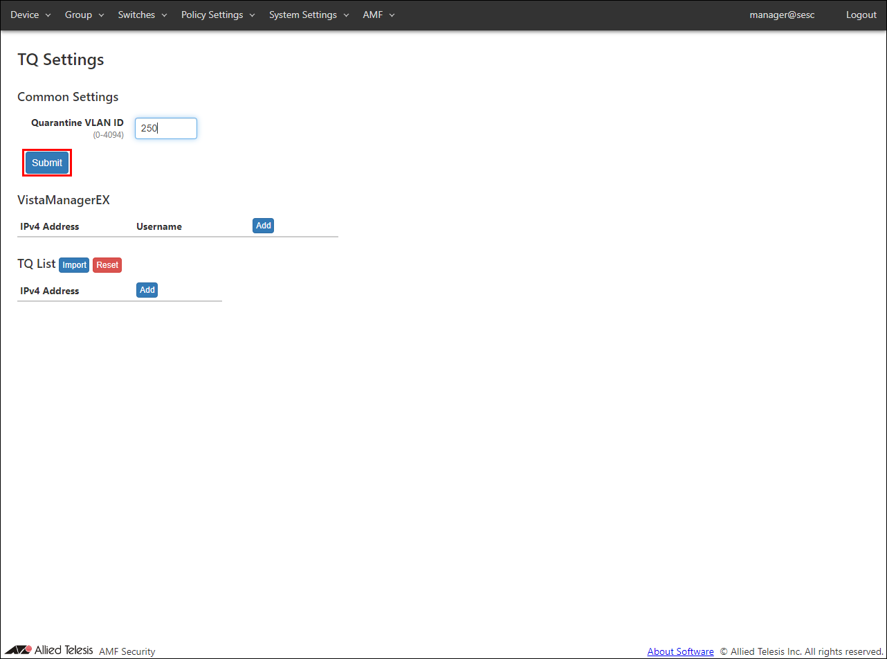
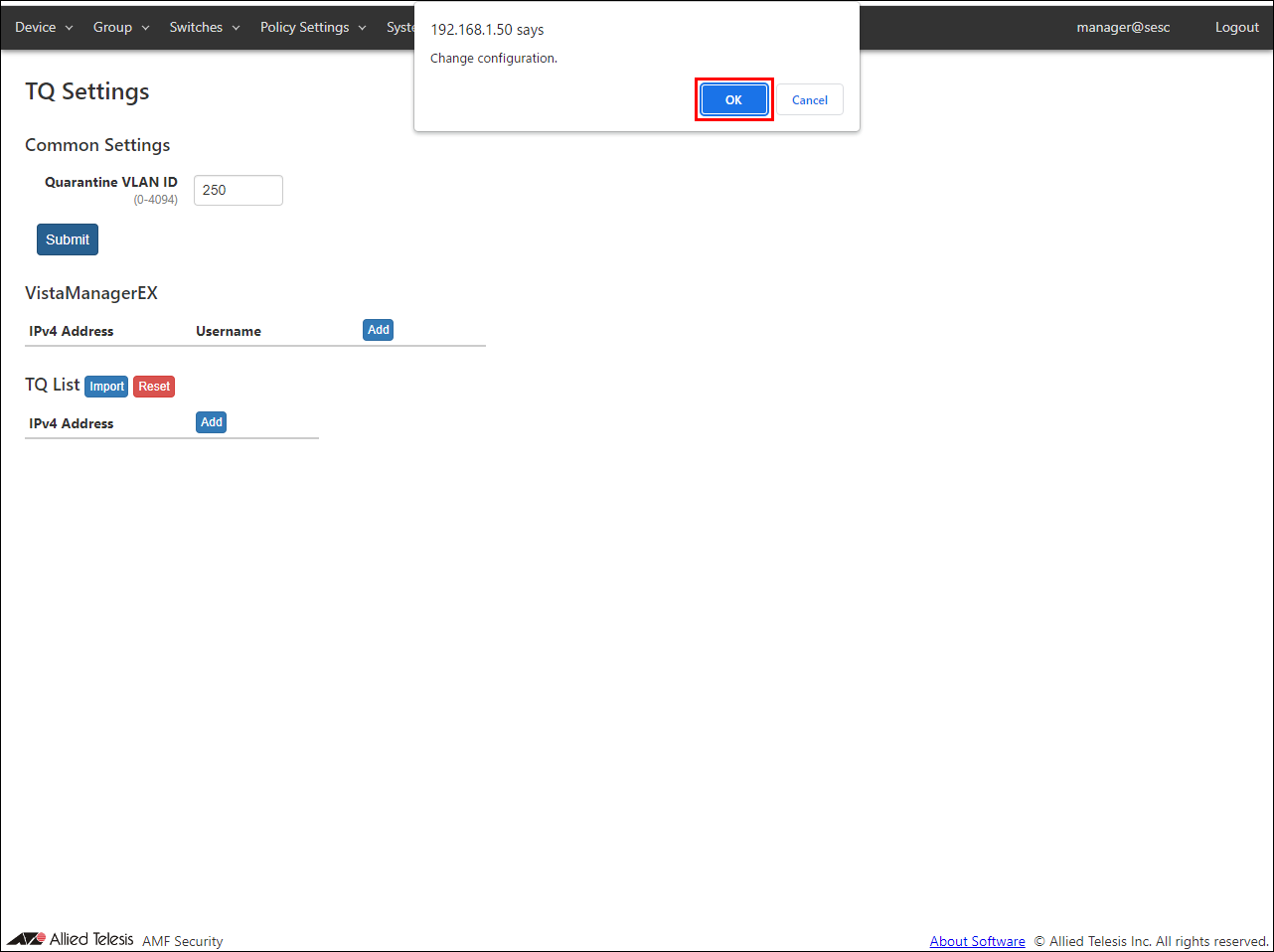
- Enter "250" for the isolated VLAN in the isolated VLAN ID of the common settings, and click the "Submit" button.
- A confirmation dialog is displayed. Click the "OK" button.
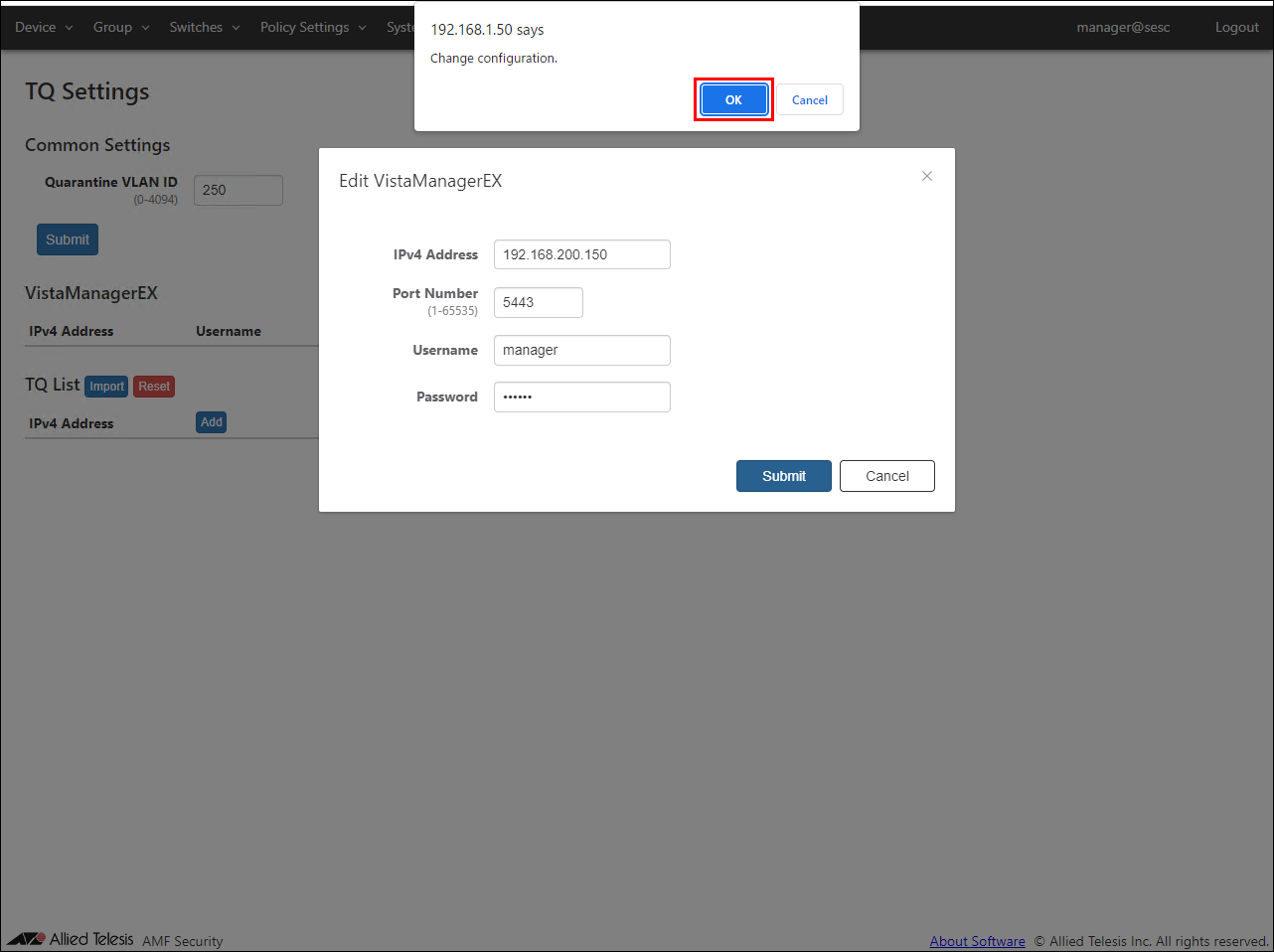
- Click the "Add" button of VistaManagerEX.
The Edit VistaManagerEX dialog is displayed.
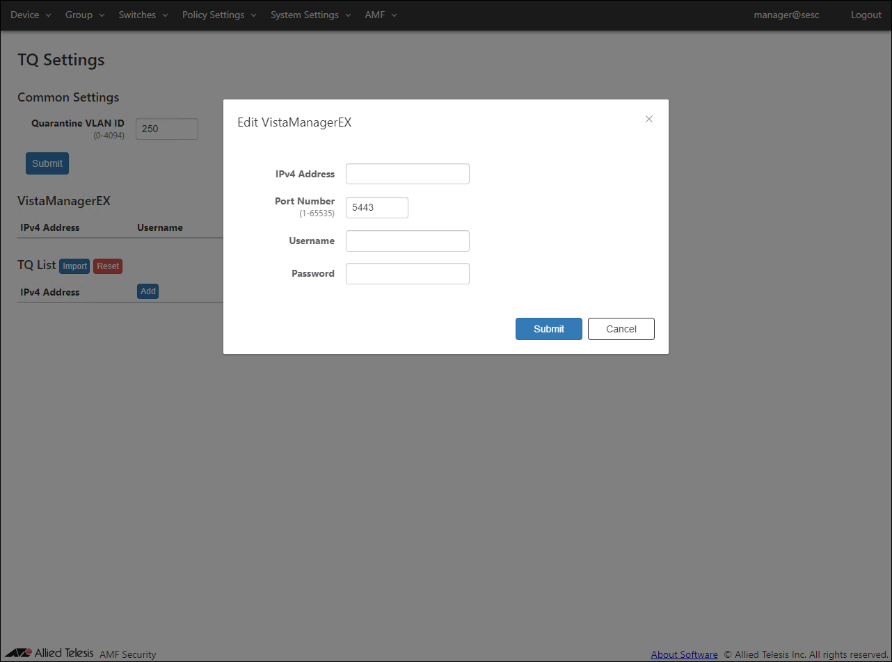
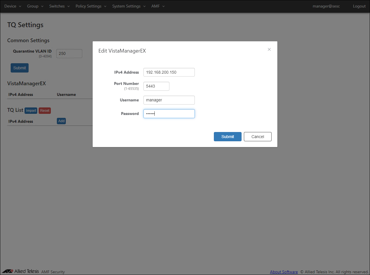
- Set the information of Vista Manager EX.
Set the following information.
Table 9: Configurable fields
Item Name Value Vista Manager EX IPv4 Address 192.168.200.150 AWC Plug-in Port Number 5443 Vista Manager EX User Name manager Vista Manager EX Password TopSecret0!
Note
For the IPv4 Address of Vista Manager EX, specify the IP Address of the Vista Manager EX server when using the Windows version.
When using the AT-VST-APL / AT-VST-VRT version, specify the IP Address of the AWC Plug-in.
- After setting the above information, click the "Submit" button.
A confirmation dialog is displayed. Click the "OK" button.
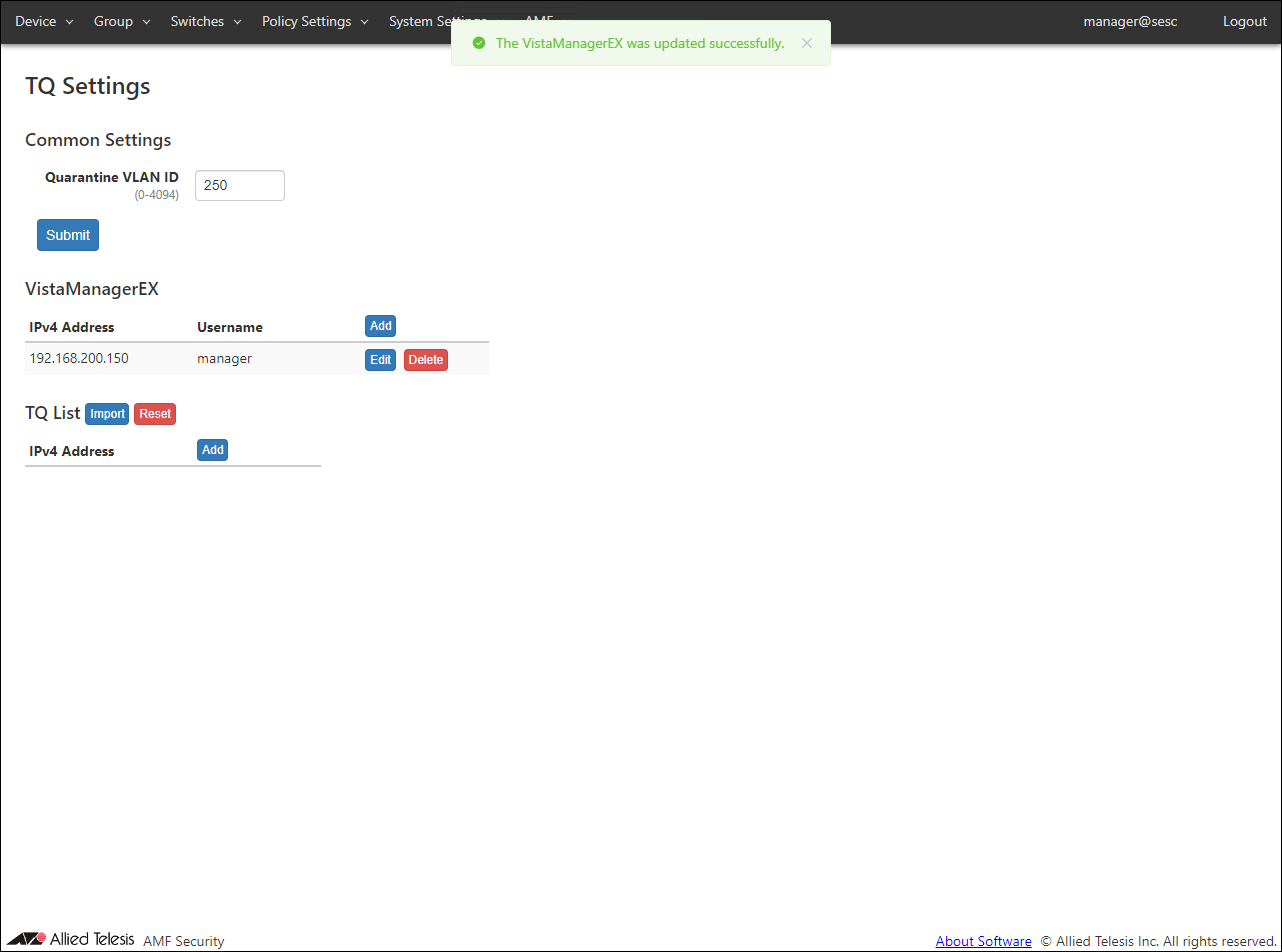
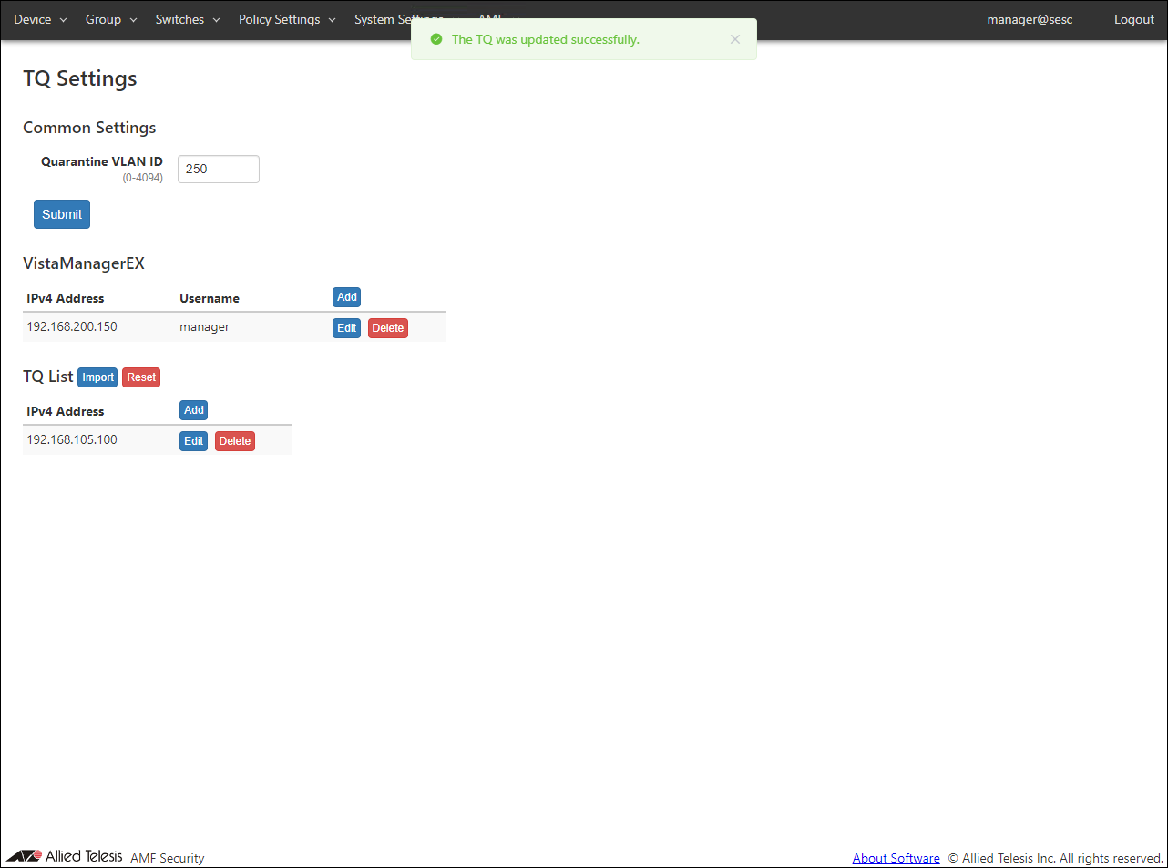
- Click the "Add" button in the TQ List.
The Edit TQ dialog is displayed.
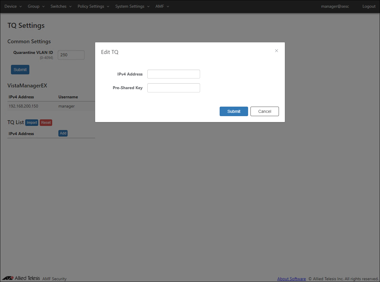
- Set the TQ information.
Set the following information.
Table 10: Configurable fields
Item Name Value TQ5403-1 IPv4 Address 192.168.105.100 Pre-Shared Key password
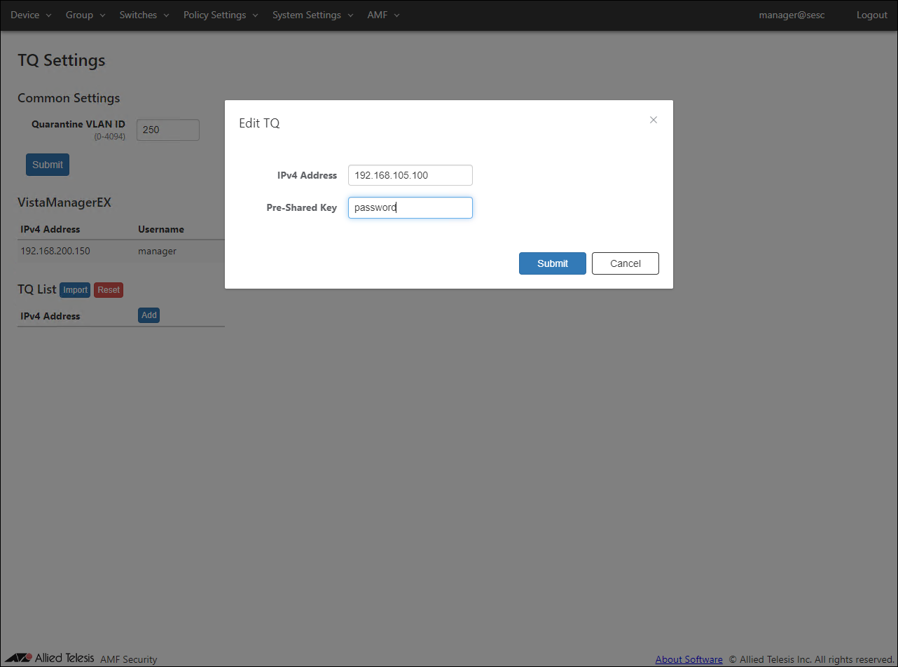
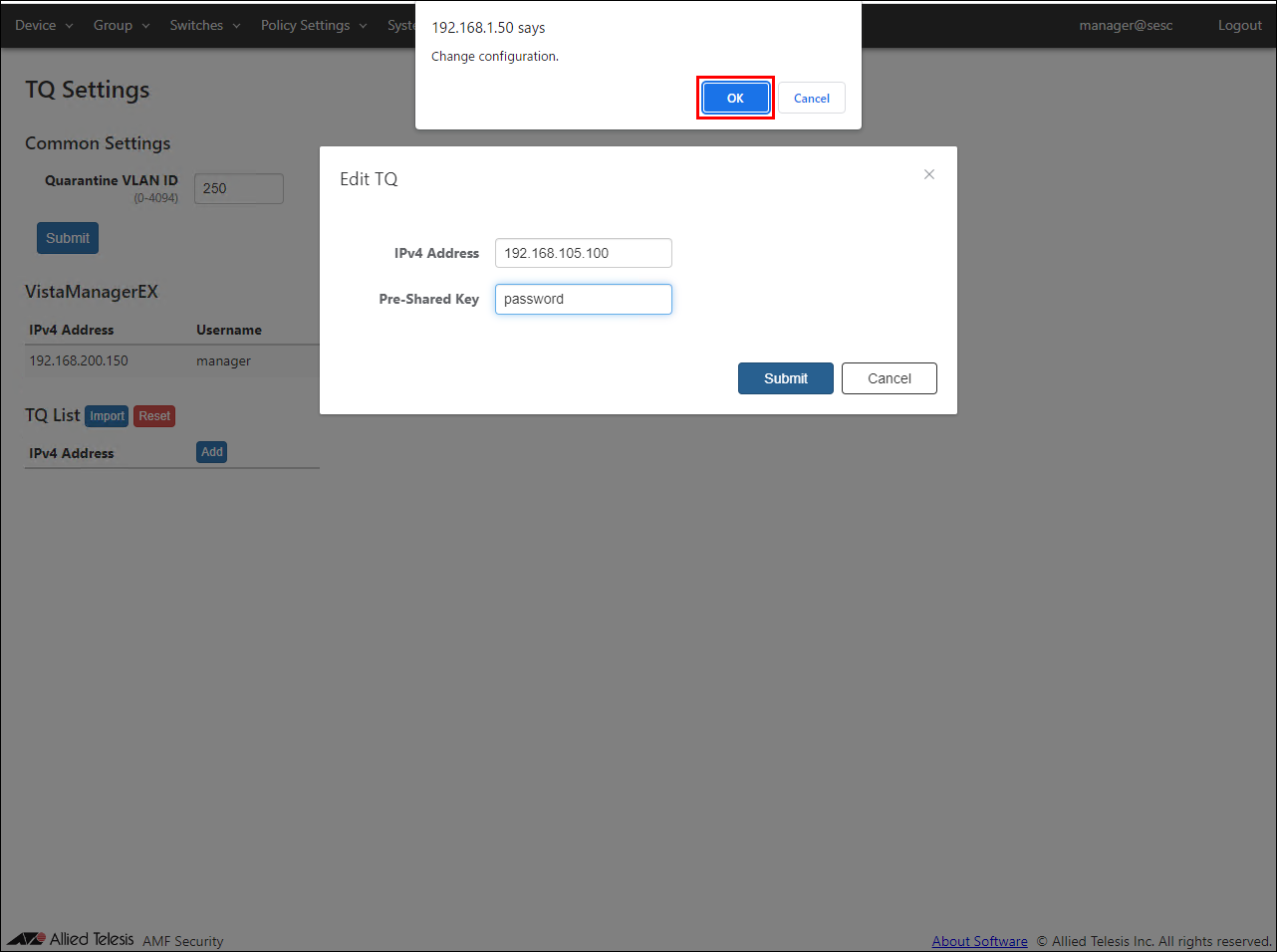
- After setting the above information, click the "Submit" button.
A confirmation dialog is displayed. Click the "OK" button.
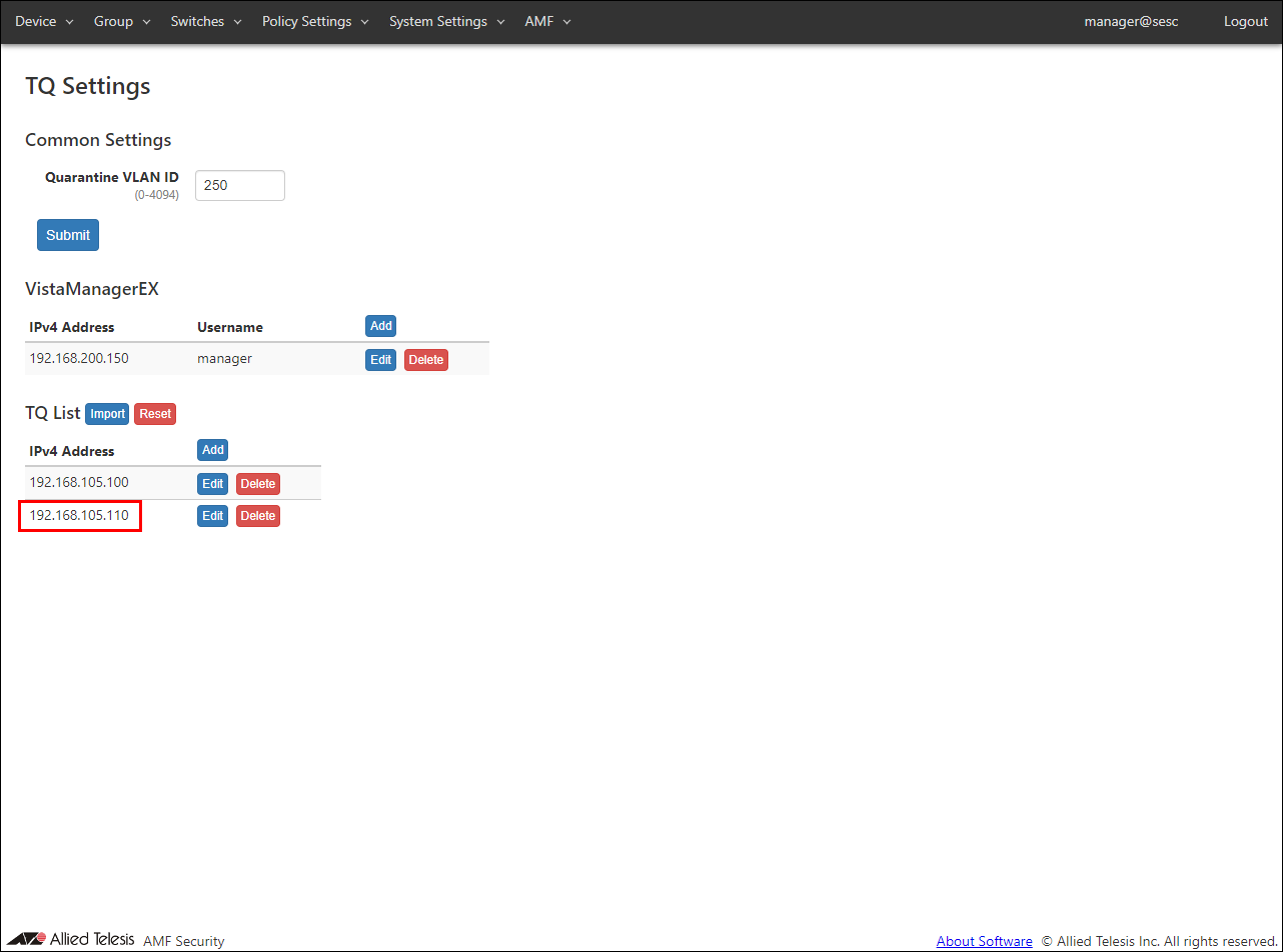
- Follow the same procedure as for the first TQ to set the second TQ.
Table 11: Configurable fields
Item Name Value TQ5403-2 IPv4 Address 192.168.105.110 Pre-Shared Key password
Note
TQ settings can be imported using a CSV file.
For the CSV file format, refer to AMF > TQ Settings.
- Display the System Settings > Trap Monitoring Settings page. Set the rules for UTM-related functions of AR3050S / AR4050S to be used as the linked application.
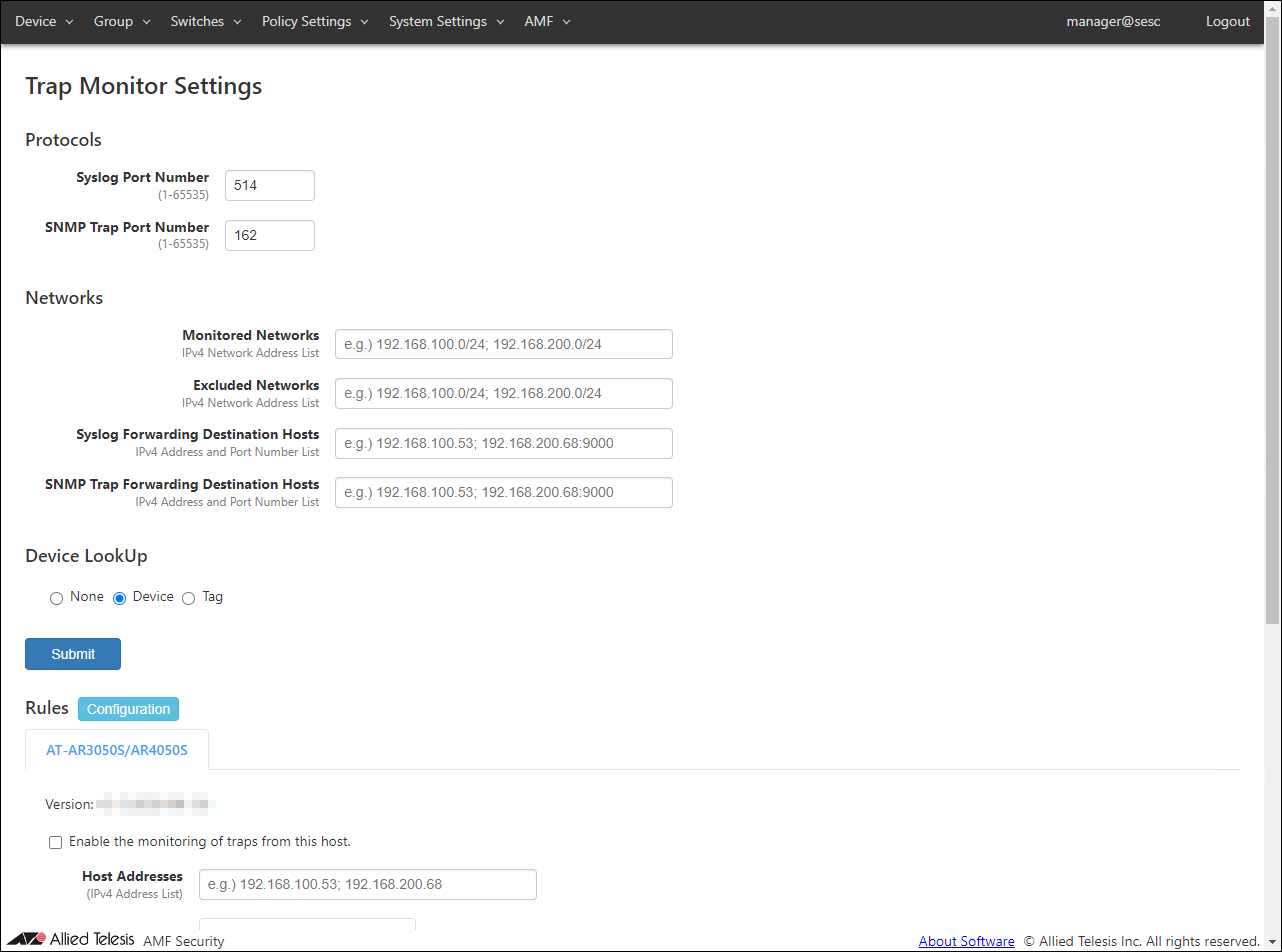
- Check the "Enable the monitoring of traps from this host." checkbox in the Rules.
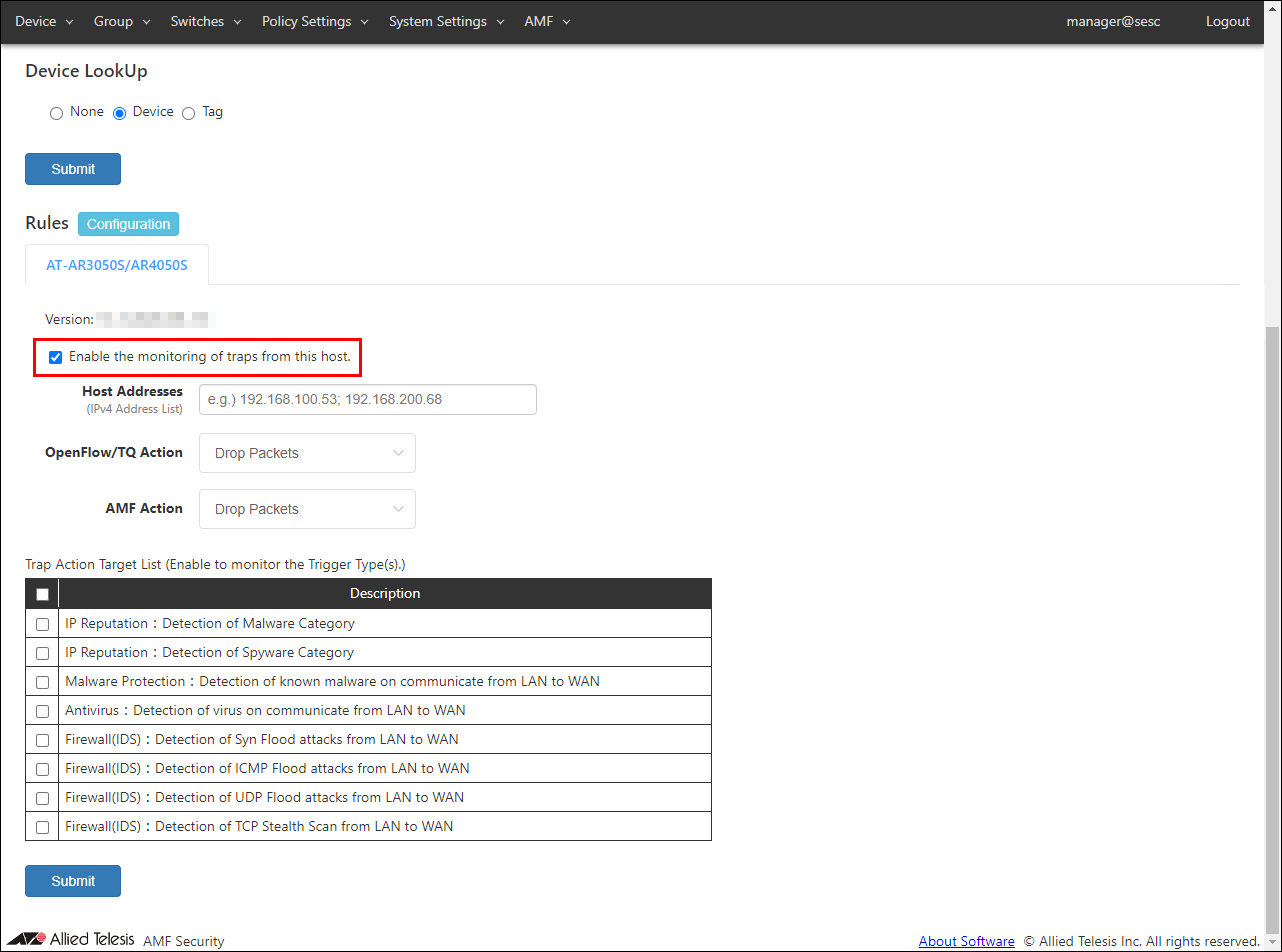
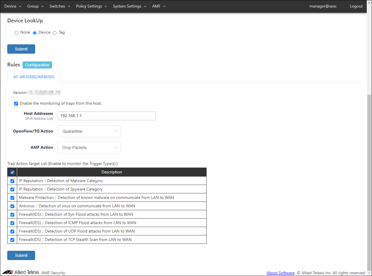
- Set the information for the AR router, action, and trap monitoring target.
Set the following information.
Table 12: Configurable fields
Item Name Value Host Addresses 192.168.1.1 OpenFlow/TQ Action Quarantine Trap Action Target List Check all
Note
The host address is set to receive only notifications from the set IP Address.
The trap monitoring target is all targeted here, but the linkage is the firewall / UTM set in the AR router.
Please refer to Configuring AT-AR3050S/AT-AR4050S for the functions that can be linked.
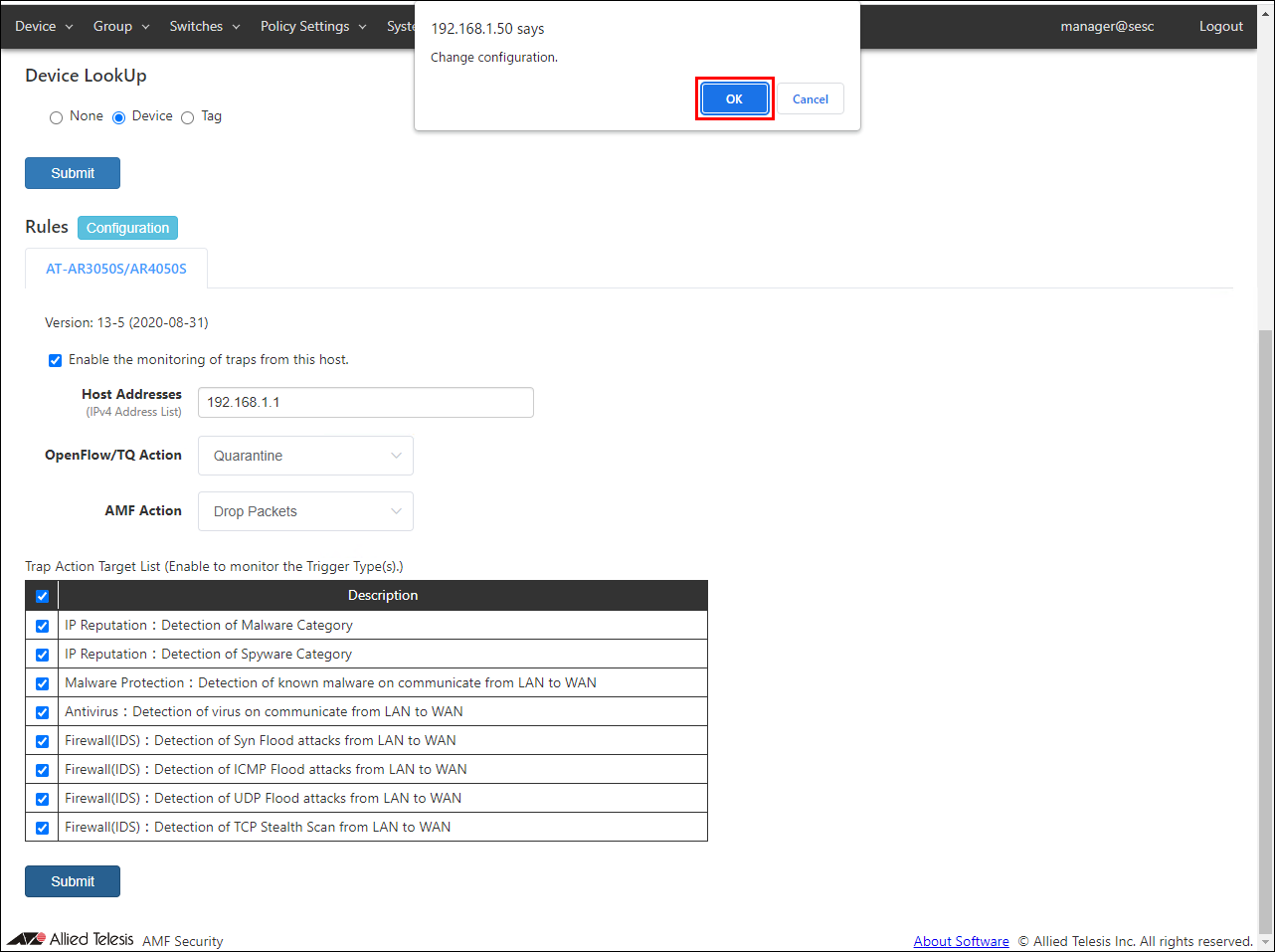
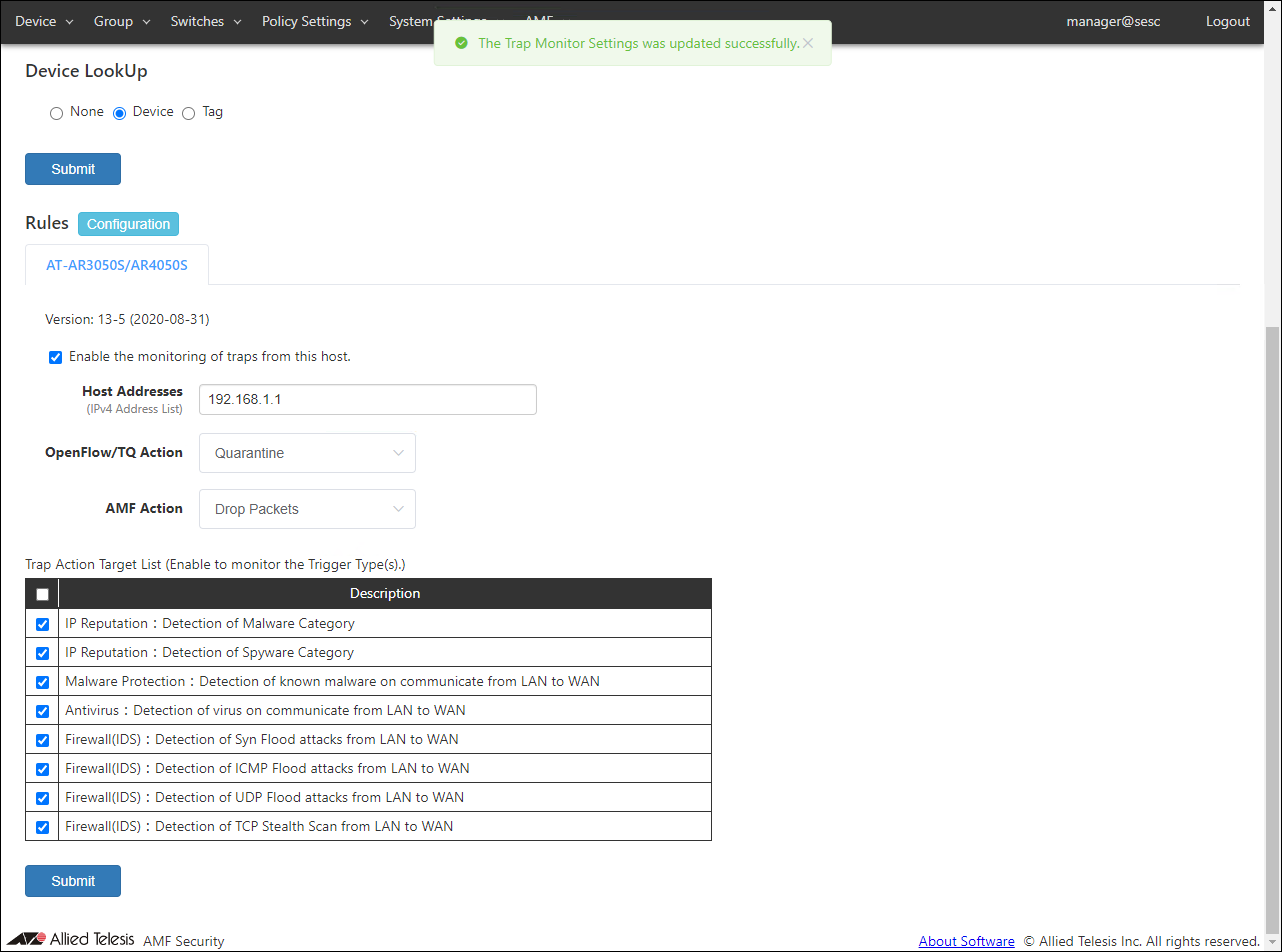
- After setting the above information, click the "Submit" button.
A confirmation dialog is displayed. Click the "OK" button.
- Register the authentication information of the device (wireless terminal).
Display the Policy Settings > Network List page and click the "Add Network" button to display the "Add Network" page.
Note
If you select WPA Enterprise with security of VAP (multi-SSID) setting of TQ, enable dynamic VLAN, and make the wireless terminal belong to the VLAN ID given by the RADIUS server on the WPA Enterprise side, you do not need to set the network policy.
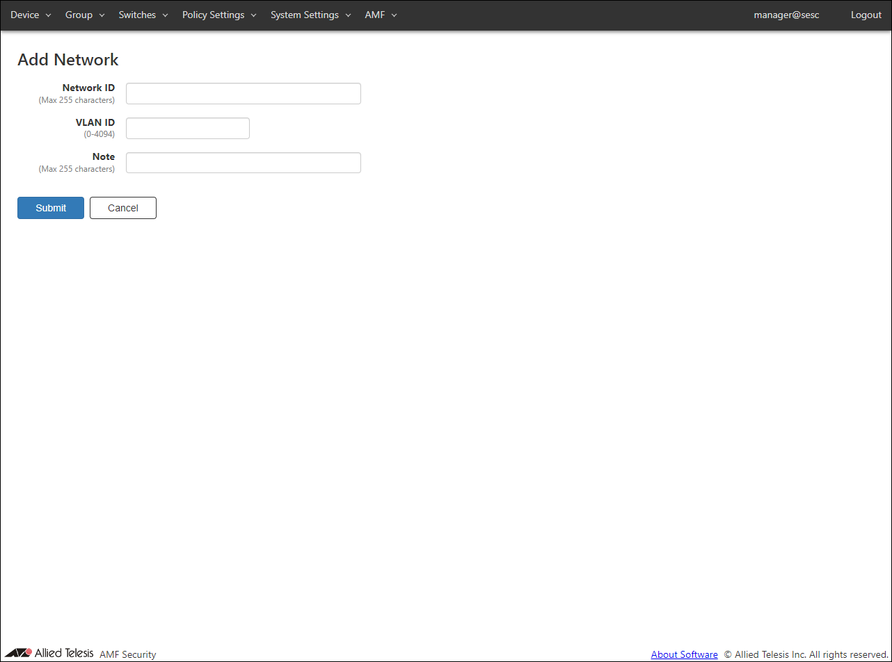
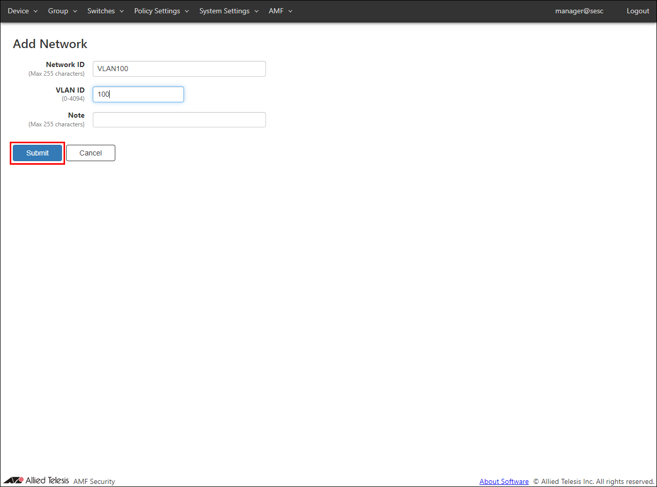
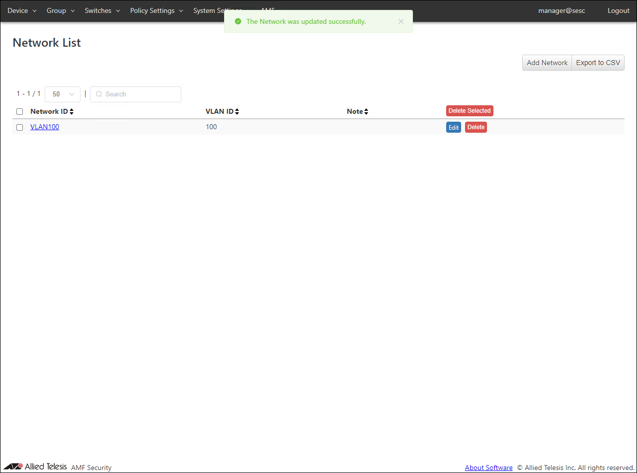
- To register VLAN100, enter the network ID and VLAN ID as follows, and click the "Submit" button.
Table 13: Configurable fields
Item Name Value Network ID VLAN100 VLAN ID 100
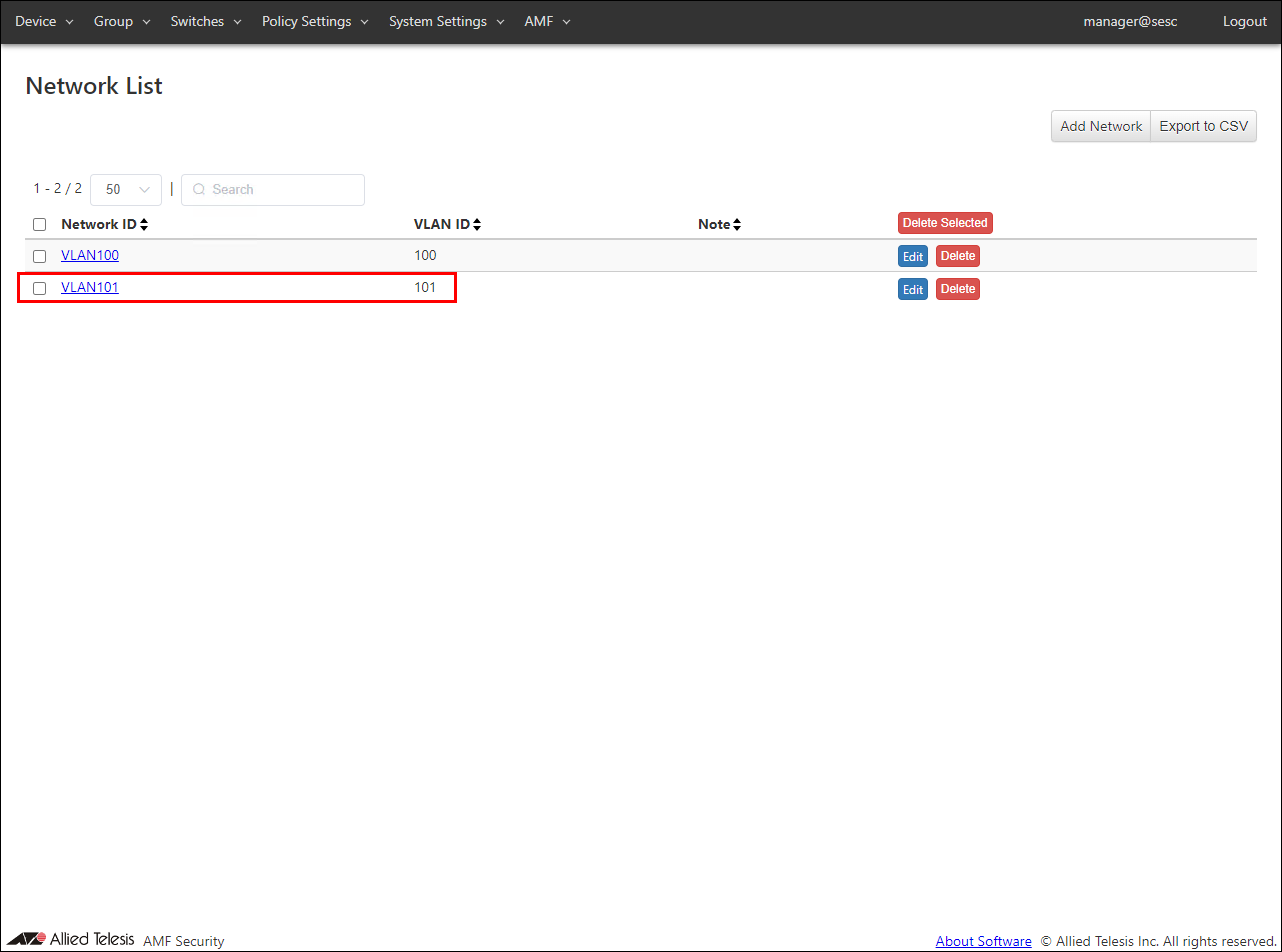
- Register VLAN101 using the same procedure as for registering VLAN100.
Table 14: Configurable fields
Item Name Value Network ID VLAN101 VLAN ID 101
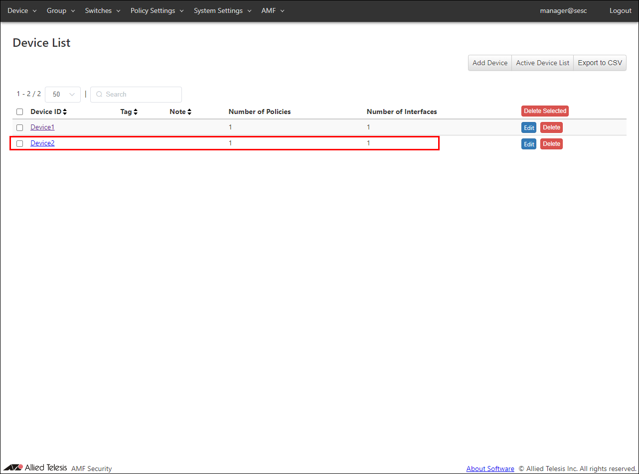
◼ Registering Device
- Register the device.
Display the Devices > Device List page and click the "Add Device" button to open the "Add Device" page.
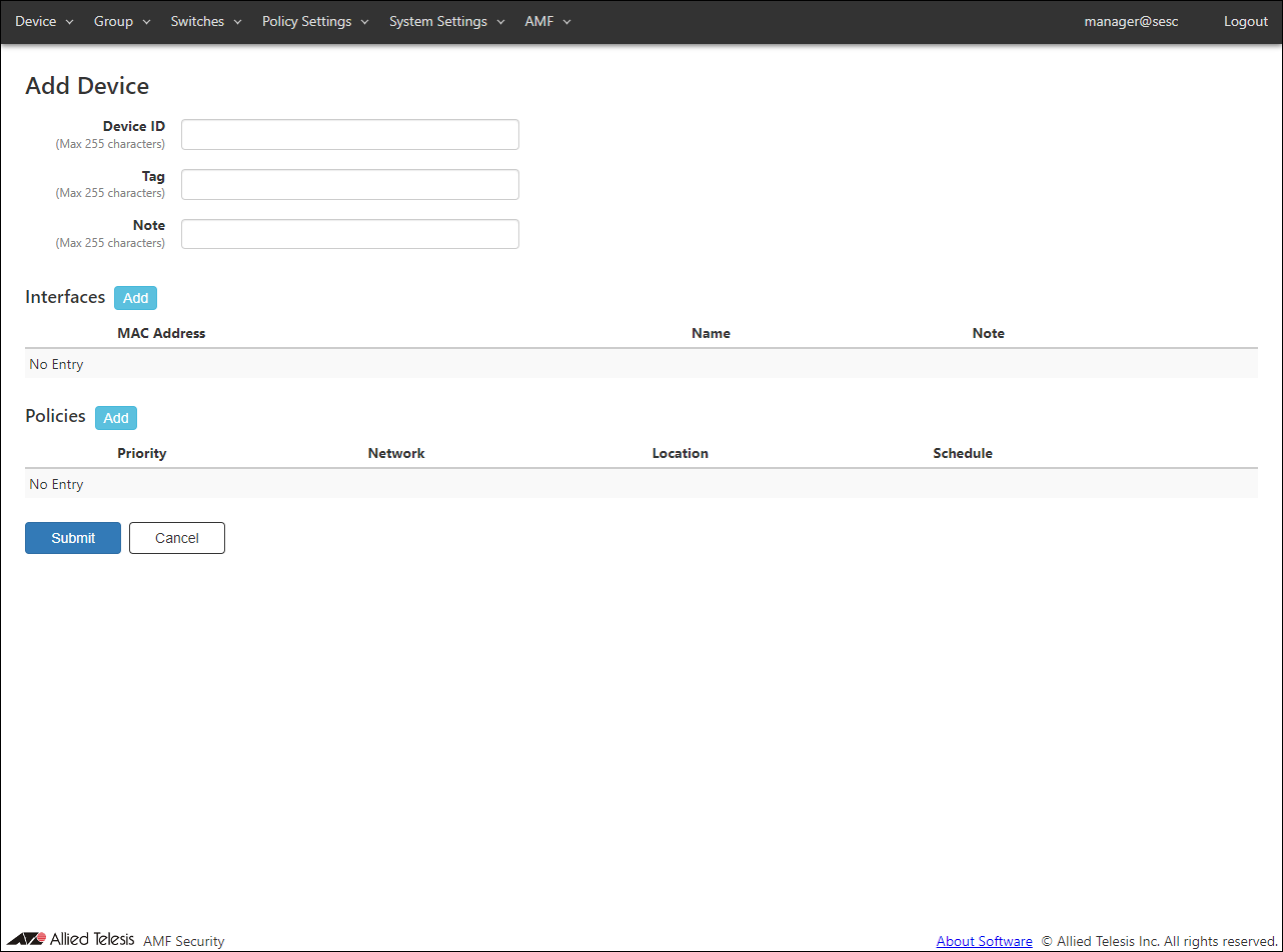
- The first to register is "Device ".
Enter "Device1" for the device ID.
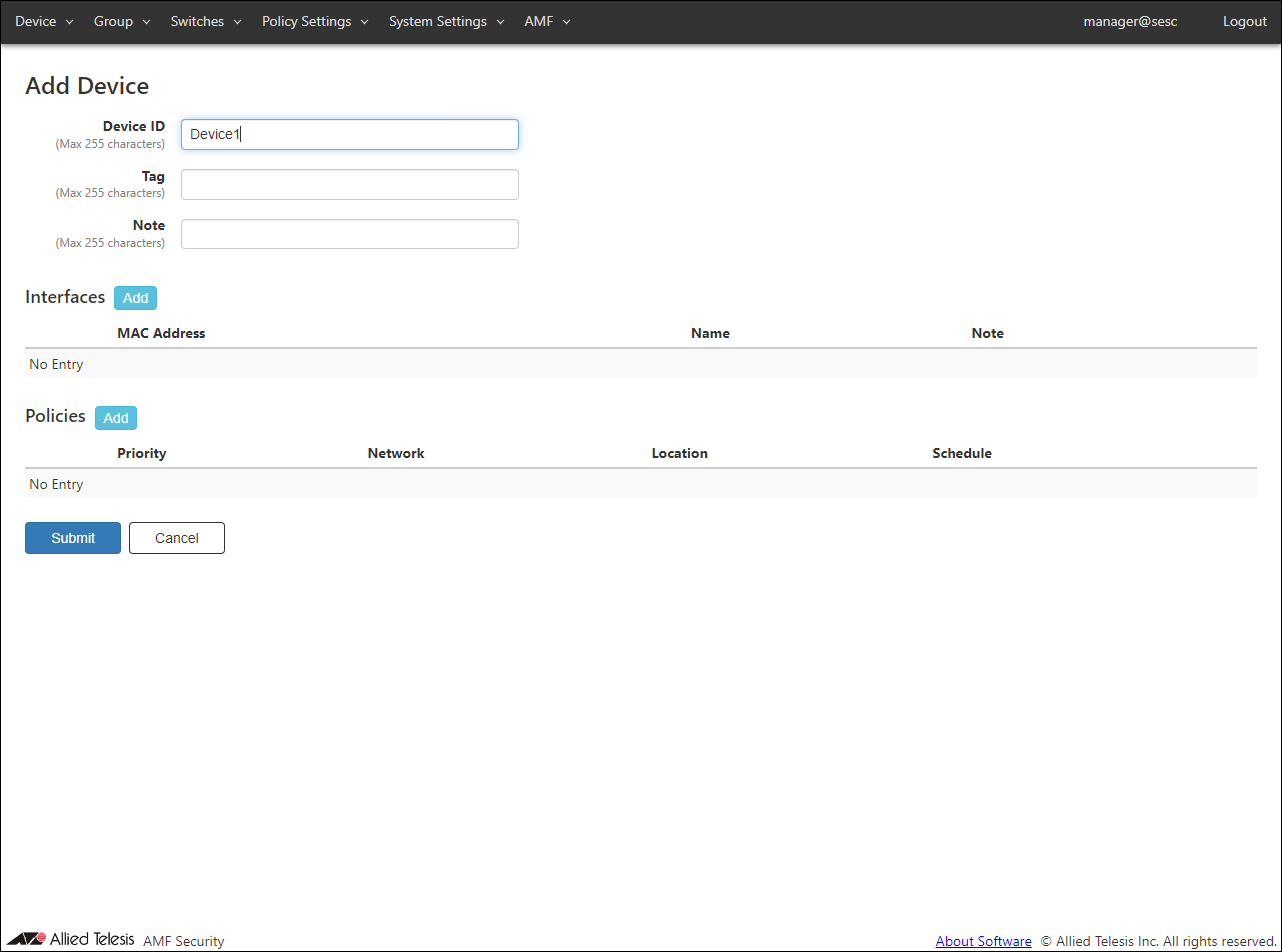
- Enter a device ID, then click "Add Interface" button to open "Edit Interface" dialog.
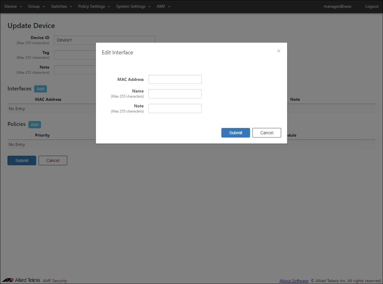
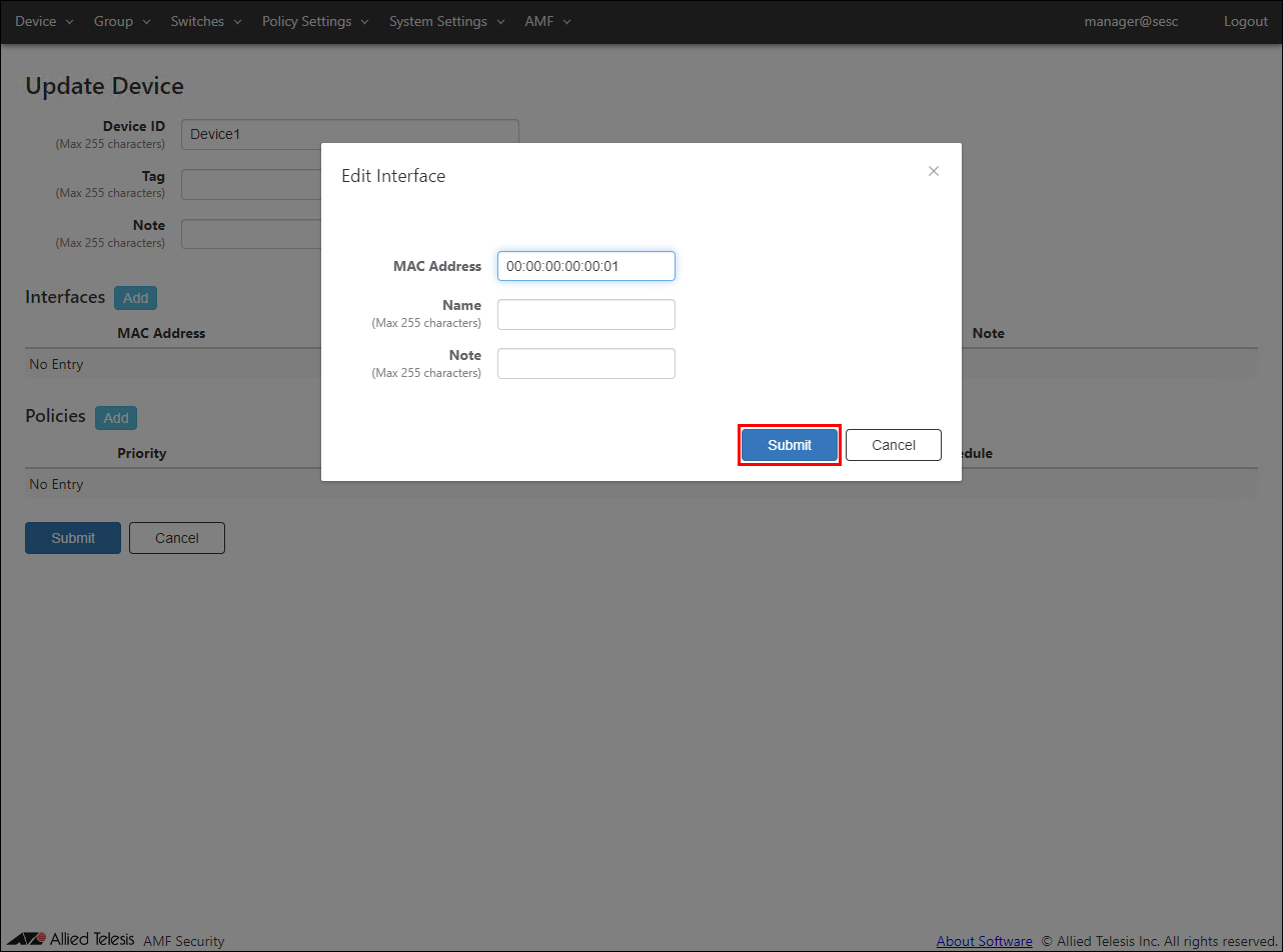
- In the same dialog, enter the device MAC Address "00:00:00:00: 00: 01" and click the "Submit" button.
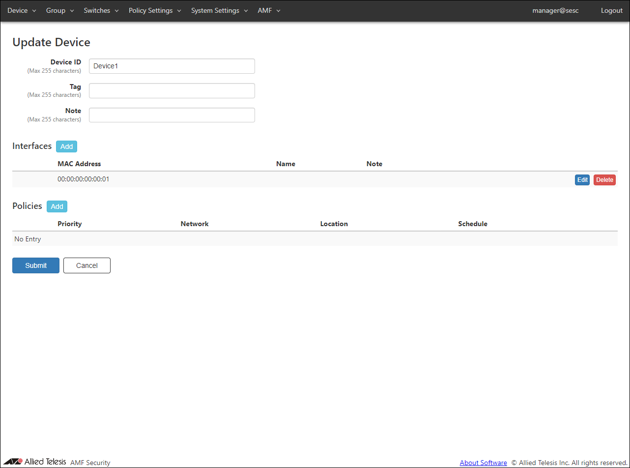
- Next, click the "Add" button in the policy column to open the "Edit Policy" dialog to specify the network to be assigned to the device.
Note
If you select WPA Enterprise with security of VAP (multi-SSID) setting of TQ, enable dynamic VLAN, and make the wireless terminal belong to the VLAN ID given by the RADIUS server on the WPA Enterprise side, you do not need to set the network policy.
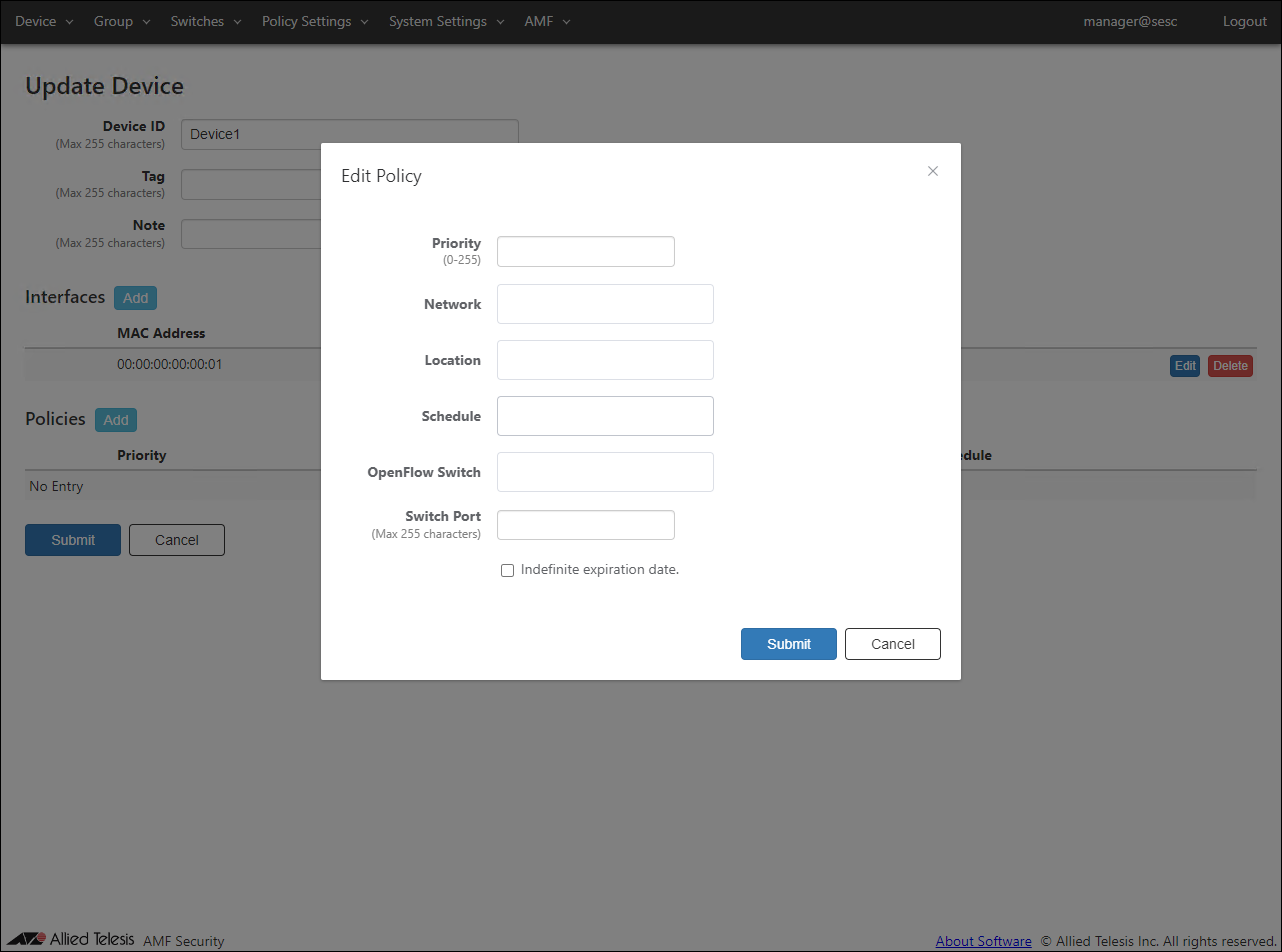
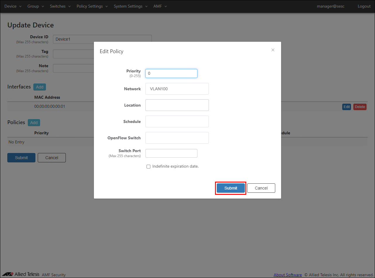
- In the same dialog, select the network "VLAN100" to assign from the drop-down list, enter the priority "0", and click the "Submit" button.
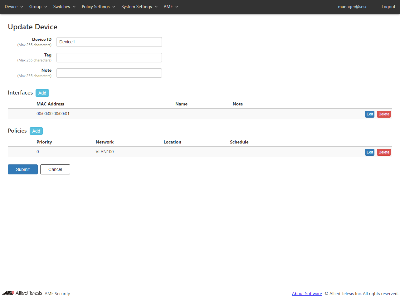
- After entering the device ID and adding the interface and policy, click the "Submit" button.
The page returns to the Devices > Device List page.

- Register "Device2" using the same procedure as for registering "Device1".
Table 15: Configurable fields
Item Name Value Device ID Device2 Interfaces 00:00:00:00:00:02 Policy priority 0 Policy network VLAN101
Configuring AR Router
- Set the log command to send threat information detected by UTM-related functions to AMF Security in a syslog message.
The source IPv4 Address for syslog messages specifies the IPv4 Address configured on the vlan1 interface.
awplus(config)# log host 192.168.200.100 ↓
awplus(config)# log host 192.168.200.100 level informational facility local5 ↓
awplus(config)# log host source vlan1 ↓
Note
The log date and time format set with the "log date-format" command can be set with either default or iso.
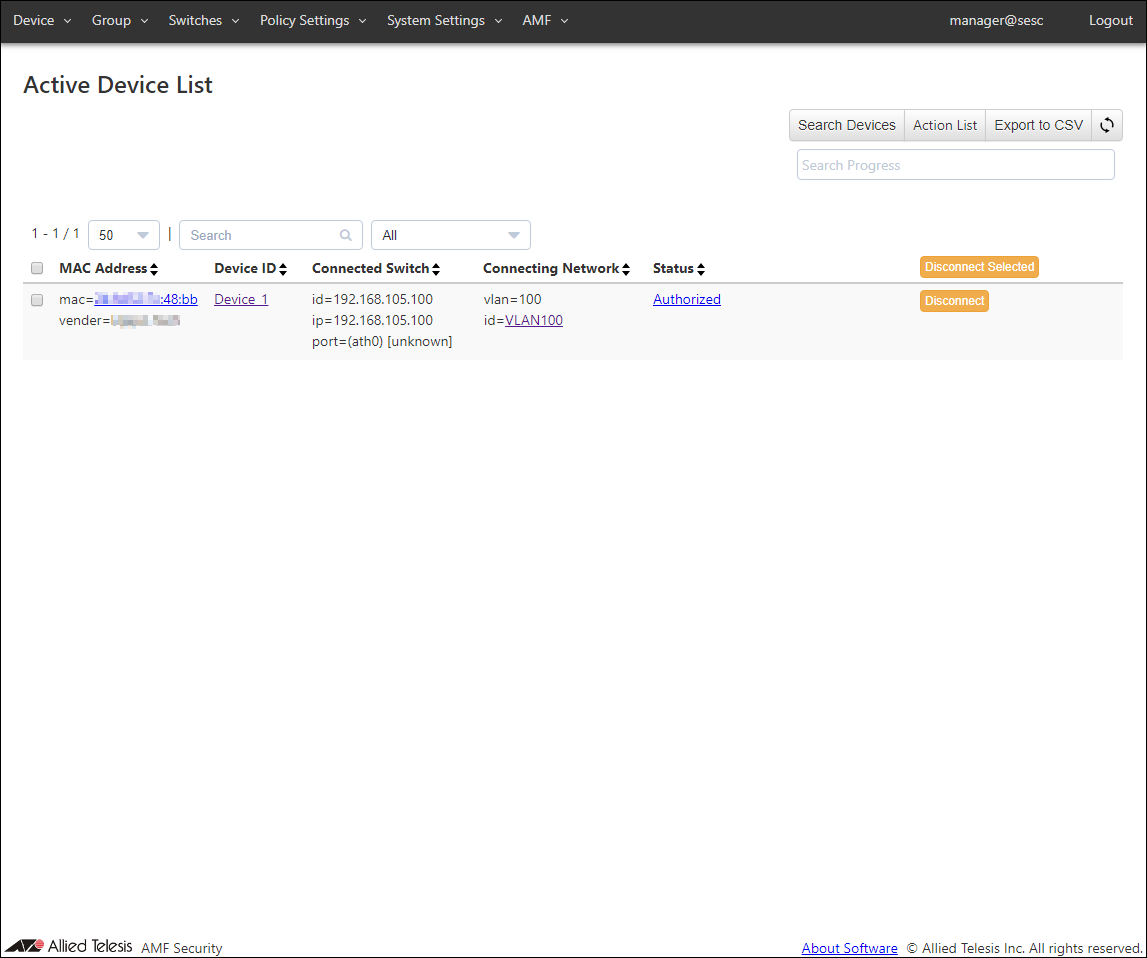
Device Authentication Result
AMF Security, a wireless terminal connected to TQ, authenticates based on the registered authentication information.You can check the authentication result on the Devices > Acctive Device List page.
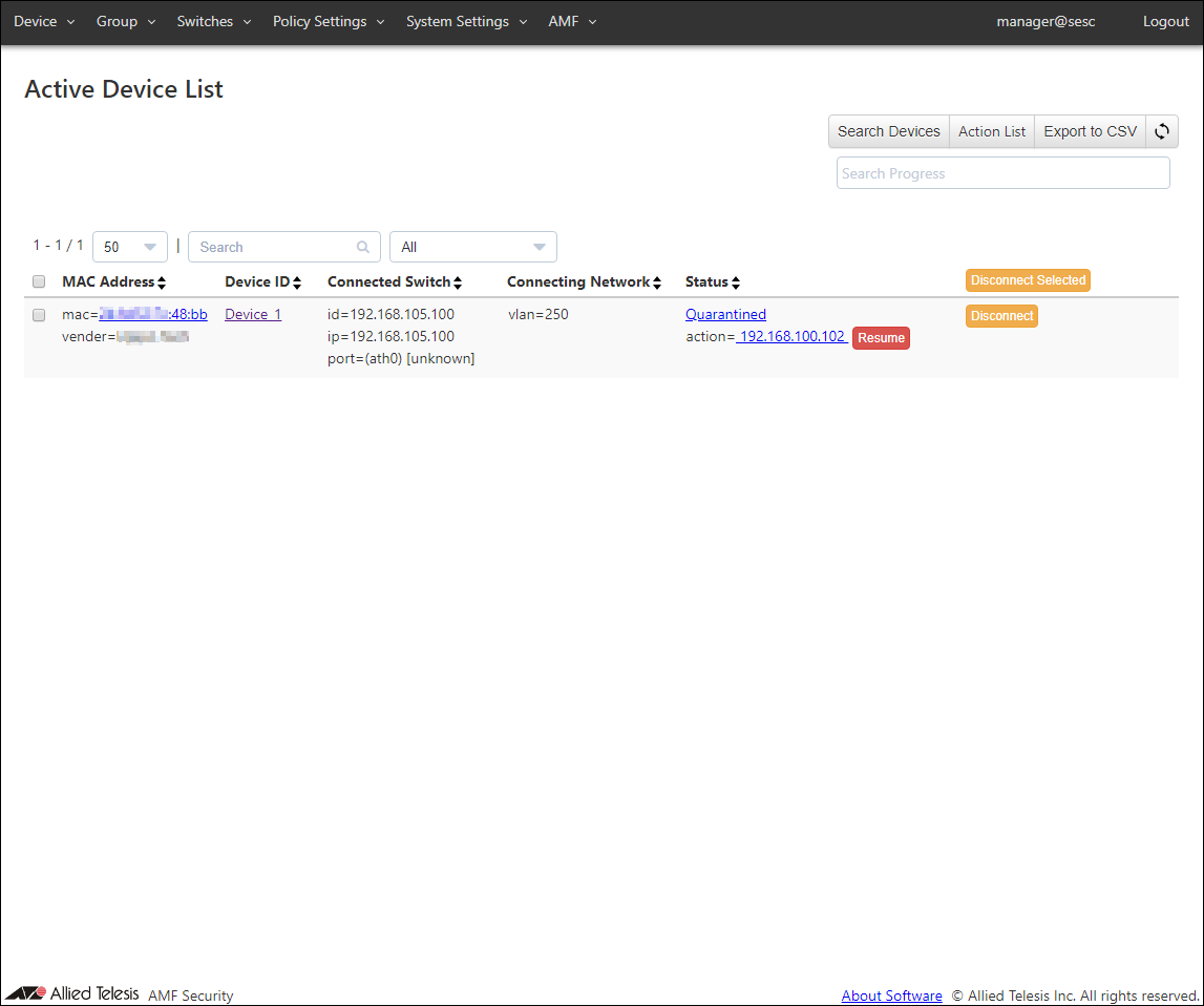
Even if the AR router detects a threat and isolates the wireless terminal, check it on the Devices > Active Device List page.
08 Jul 2022 16:52