Floor Map Detail [Wireless Status View]
Clicking on a floor map panel or selecting a specific floor map from the floor map dropdown menu will show the "Floor Map Details" page.
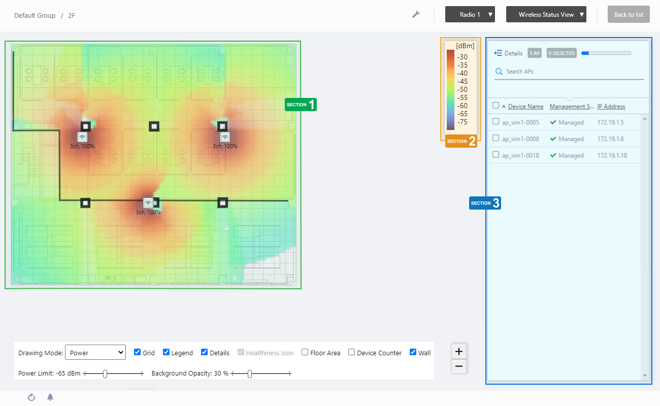
The floor map is displayed in the center of the Content section and a list of APs is shown on the right side of the Content section.
NoteThe status displayed for an unreachable AP is the status that was last collected.
NoteIf you try to move an AP icon, it may move to an unintended position and your mouse cursor and the icon may become out of sync.
If this occurs, release your mouse button and drag the icon again.
NoteIf you try to place an AP on a floor map that was deleted by another user, you will be brought back to the "Floor Map Details" page without any error message. In such cases, please check if the floor map still exists on the "Floor Map List" page.
Wireless Status View
Displays wireless signal Comfort Level, Power (signal strength) and Channel on a floor map.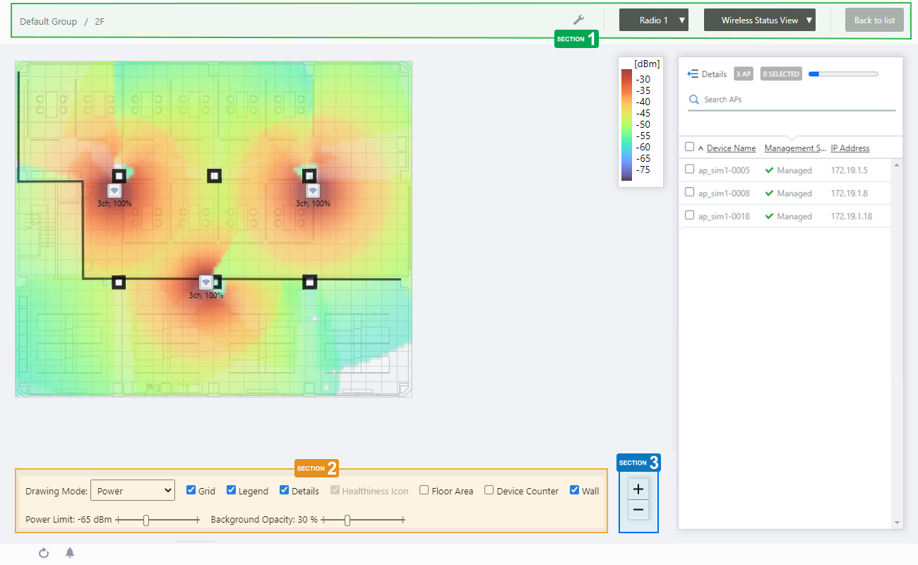
In the floor map control described below, you can switch between Comfort Level, Power, and Channel modes from the Drawing Mode drop-down menu.
Common Items
The display items common to the Comfort Level, Power, and Channel modes are shown below.Section 1
| Item Name | Description |
|---|---|
| Management Group / Floor Map Group | The floor map name and the management group of the selected floor map will be displayed. |
| "Spanner" icon | Hovering the mouse cursor over the Spanner icon shows a dropdown menu including some operations for managed APs. Select APs by checking on the AP list or clicking the AP icons on the floormap, you can then execute the following operation for the selected APs.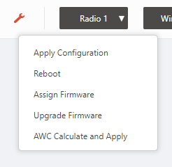
|
| Radio dropdown menu | Lets you select a radio band to show on the map, from Radio 1, 2 or 3. |
| View Selection dropdown menu | Lets you change what information is displayed on the Floor Map Details screen.
|
| "Back to list" button | Click to return to the Floor Map List screen. |
Section 2
In Wireless Status View, the "Healthiness Icon" is disabled.

| Item Name | Description |
|---|---|
| Drawing Mode | Lets you select what to show on the heatmap. The options are: Comfort Level, Power (signal strength) and Channel. The default is "Comfort Level". |
| Grid | Lets you enable or disable grid lines on the floor map. Checking this shows grid lines on the floor map. |
| Legend | Lets you enable or disable the legend. Check to display. |
| Details | Whether to display the list of placed APs. Check to display. |
| Floor Area | This item is not supported. |
| Device Counter | This item is not supported. |
| Wall | If walls have been created on the floor map (using the Edit Wall page), lets you choose whether to display the walls. Check to display.NoteIf walls have been defined, attenuation by the walls takes effect over the heat map even when this control is left unchecked. |
| Power Limit | Specify the minimum signal strength to show in colors on the heatmap. Disabled in comfort level mode. |
| Opacity | Specify the opacity of the floor map background image. |
Section 3
Zoom In/Out buttons.
You can zoom in (+) or zoom out (-) of the floor map display. You can also use the mouse wheel scroll to zoom in or out.

Comfort Level Mode
The floor is color-coded by comfort level, based on five comfort parameters: Channel Availability, Client Capacity, Connection Stability, Wi-Fi signal stability, and Airtime Capacity.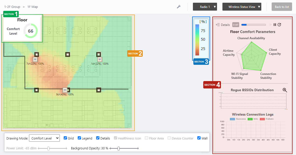
Section 1
Displays numerical values (in %) and graphs of the comfort level of the entire floor, as independently calculated by AWC Plug-in.
Clicking on any point on the floor map switches to a display of the comfort level at that point.
Section 2
| Item Name | Description |
|---|---|
| Floor Map (Background) | The map image specified when you created the map is shown. You can place icons for the APs in the righthand-side list. |
| Wireless AP Icon | AP icons placed on the map is shown. Below each icon, the channel, radio utilization and transmit power for the AP are displayed. Notes on icons:
|
| Rogue AP Icon | If Unmanaged AP Detection is enabled, this represents the estimated location of the unmanaged APs that are particularly impacting. When you hover the mouse pointer over the icon, the SSID, BSSID, channel, radio strength (RSSI), and detection time sent out by the concerned unmanaged AP will pop up. 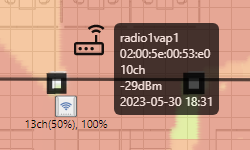
|
Section 3
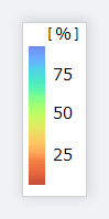
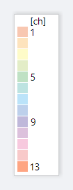
Shows the heatmap legend.
It shows the relationship between colors and comfort level.
The legend can be made invisible or visible by using a checkbox in the floor map control section at the bottom of the page.
Section 4
| Item Name | Description |
|---|---|
| Details | Disabled in comfort level mode. |
| X AP | Shows the number of APs placed on the floor map. |
| Refresh Timer | Shows the status of the timer that automatically refreshes the page with the blue progress bar. The list is automatically refreshed at the interval configured on "Refresh Rates" > "Floor MAP (Wireless Status)" in the User Management menu. (The default is 1 minute.) |
| Comfort Parameters chart | The following five comfort parameters are displayed as a radar chart.
By clicking on each parameter in the graph, you can exclude or re-include the relevant parameter from evaluation in the heat-map display. The parameter name excluded from evaluation is grayed out. If the comfort level is low, hover the mouse pointer over the caution icon on the left side of the title to see suggestions for improvement. |
| Rogue BSSIDs Distribution | Displays the radio waves of rogue APs emitted by wireless devices other than managed APs detected by the APs on the floor map in the past hour as channels on the horizontal axis and output strength (RSSI) on the vertical axis. Click on the graph to enlarge. NoteIn order to view this graph, "Rogue AP Detection" in the Wireless IDS/IPS Settings and "Neighbor AP Detection" in the AP profile must be set to enabled. |
| Wireless Connection Logs | Displays the number of success logs such as associations, failure logs such as disconnections, and information logs such as channel blanket handovers of wireless clients to the APs on the floor map over the past hour. |
Signal Power Mode
Section 1
| Item Name | Description |
|---|---|
| Floor Map (Background) | The map image specified when you created the map is shown. You can place icons for the APs in the righthand-side list. |
| Wireless AP Icon | AP icons placed on the map is shown. Below each icon, the channel and transmit power for the AP are displayed. Notes on icons:
|
Section 2
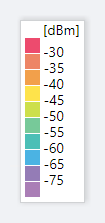
Shows the heatmap legend.
This shows the relationship between colors and signal strength or channels.
The legend can be made invisible or visible by using a checkbox in the floor map control section at the bottom of the page.
Section 3
| Item Name | Description |
|---|---|
| Details | Clicking this shows the device's model, MAC address, AP Profile, the number of associated clients for each radio, and tags, as well as the Device name, Management Status and IP address that are shown on the non-detailed view. Clicking this again returns you to the default non-detailed view. |
| X AP | Shows the number of APs placed on the floor map. |
| Refresh Timer | Shows the status of the timer that automatically refreshes the page with the blue progress bar. The list is automatically refreshed at the interval configured on "Refresh Rates" > "Floor MAP (Wireless Status)" in the User Management menu. (The default is 1 minute.) |
| Search Wireless AP | Entries in the list can be filtered by entering a partial string in the search box. The Search field lets you enter a partial string to match. The screen displays entries with that string in one of the following fields: "Device Name", "Management Status", "IP address", "MAC address" or "AP Profile" fields. To remove the filter, delete the string from the search field and press enter. NoteThe search is case-sensitive. |
| Filter by tag | Lets you filter APs with tags. Clicking tags uses tags to filter the list. Clicking them again removes the filter. Clicking "Clear filter" removes the filter for all tags. NoteTo select tags, you have to switch the list to detailed mode (by clicking "View Details"). |
| Tag | All tags are displayed under the "Search Wireless AP" box. |
| Status Icon | When the AP is managed by the AWC Plug-in, a green checkmark is displayed. When the AP is not managed by the AWC Plug-in, a red triangle is displayed. |
| Device Name | Shows the name given to the AP. |
| Management Status | Shows the Management Status of the AP. |
| IP Address | Shows the AP's IP address. |
Channel Mode
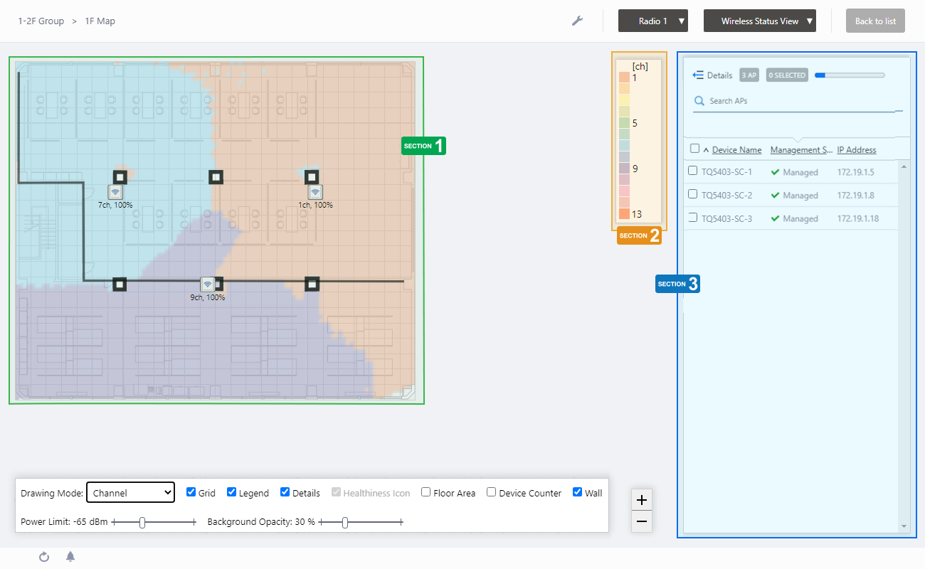
Section 1
| Item Name | Description |
|---|---|
| Floor Map (Background) | The map image specified when you created the map is shown. You can place icons for the APs in the righthand-side list. |
| Wireless AP Icon | AP icons placed on the map is shown. Below each icon, the channel and transmit power for the AP are displayed. Notes on icons:
|
Section 2
Shows the heatmap legend.
It shows the relationship between colors and channels.
The legend can be made invisible or visible by using a checkbox in the floor map control section at the bottom of the page.
Section 3
| Item Name | Description |
|---|---|
| Details | Clicking this shows the device's model, MAC address, AP Profile, the number of associated clients for each radio, and tags, as well as the Device name, Management Status and IP address that are shown on the non-detailed view. Clicking this again returns you to the default non-detailed view. |
| X AP | Shows the number of APs placed on the floor map. |
| Refresh Timer | Shows the status of the timer that automatically refreshes the page with the blue progress bar. The list is automatically refreshed at the interval configured on "Refresh Rates" > "Floor MAP (Wireless Status)" in the User Management menu. (The default is 1 minute.) |
| Search Wireless AP | Entries in the list can be filtered by entering a partial string in the search box. The Search field lets you enter a partial string to match. The screen displays entries with that string in one of the following fields: "Device Name", "Management Status", "IP address", "MAC address" or "AP Profile" fields. To remove the filter, delete the string from the search field and press enter. NoteThe search is case-sensitive. |
| Filter by tag | Lets you filter APs with tags. Clicking tags uses tags to filter the list. Clicking them again removes the filter. Clicking "Clear filter" removes the filter for all tags. NoteTo select tags, you have to switch the list to detailed mode (by clicking "View Details"). |
| Tag | All tags are displayed under the "Search Wireless AP" box. |
| Status Icon | When the AP is managed by the AWC Plug-in, a green checkmark is displayed. When the AP is not managed by the AWC Plug-in, a red triangle is displayed. |
| Device Name | Shows the name given to the AP. |
| Management Status | Shows the Management Status of the AP. |
| IP Address | Shows the AP's IP address. |
Arranged AP List (Detail)
Clicking "Details" at the top of the list of placed APs on the "Floor Map Details" page extends the list to show additional information such as Device Type and AP Profile.Information displayed on the list can be switched between "System info", "Radio info" and "Client info". By default, each AP's system information is displayed.
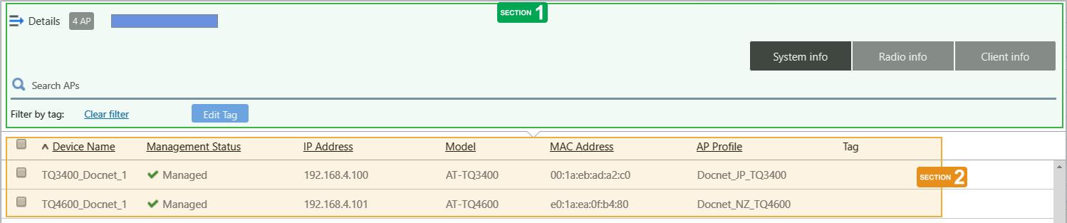
Section 1
| Item Name | Description |
|---|---|
| Details | Clicking "Details" again on the extended list shrinks the list to its default size. |
| X AP | Shows the number of wireless APs placed on the floor map. |
| Refresh Timer | Shows the status of the timer that automatically refreshes the page with the blue progress bar. The list is automatically refreshed at the interval configured on "Refresh Rates" > "Floor MAP (Wireless Status)" in the User Management menu. (The default is 1 minute.) |
| Search Wireless AP | The Search field lets you enter a partial string to match. The screen displays entries with that string in one of the following fields: "Device Name", "Management Status", "IP address", "MAC address" or "AP Profile" fields. To remove the filter, delete the string from the search field and press enter. NoteThe search is case-sensitive. |
| "System Information" button | Switches the list content to system information for the APs placed on the floor map. |
| "Wireless Information" button | Switches the list content to the wireless configuration of the APs placed on the floor map. |
| "Client Info" button | Switches the list content to the number of clients (per radio) connected to each AP placed on the floor map. |
| Filter by tag | Lets you filter APs with tags. Clicking tags uses tags to filter the list. Clicking them again removes the filter. Clicking "Clear filter" removes the filter for all tags. |
| Tag | All tags are displayed under the "Search Wireless AP" box. |
| "Tag" button | Lets you edit tags for the selected APs. To add the same tags to the APs and the floor map, check "Add the same tags to the floor map". NoteIf you paste a tag string from the clipboard, not all text may be visible. In that case, press Enter to make a tag from the entire pasted string. NotePasting a tag containing a newline is not supported. NoteTag names may be truncated in the tag filter list on the Devices Map, Floor Map Details and Device Search pages. To avoid this, use shorter names for the tags.
|
Section 2
| Item Name | Description |
|---|---|
| System Info | |
| Checkbox | To edit tags for APs, use the checkboxes to select APs and then click the "Edit Tags" button. |
| Device Name | Shows the name given to the AP. |
| Management Status | Shows the Management Status of the AP. |
| IP Address | Shows the AP's IP address. |
| Model | Shows the model name of the AP. |
| MAC Address | Shows the device's MAC address. |
| AP Profile | Shows the AP Profile assigned to the AP. |
| Tag | Shows the tags set on the AP. |
| Radio info | |
| Device Name | Shows the name given to the AP. |
| Channel (Radio1) Channel (Radio2) Channel (Radio3) |
Shows the channel used on each radio band of the AP. |
| Tx Power (Radio1) Tx Power (Radio2) Tx Power (Radio3) |
Shows the transmit power for each radio band of the AP. |
| Client info | |
| Device Name | Shows the name given to the AP. |
| Associated Clients (Radio1) Associated Clients (Radio2) Associated Clients (Radio 3) |
Shows the number of clients (per radio band) connected to the AP. |
12 Jul 2024 09:31