Floor Map
This page allows you to create floor maps to manage APs more efficiently.
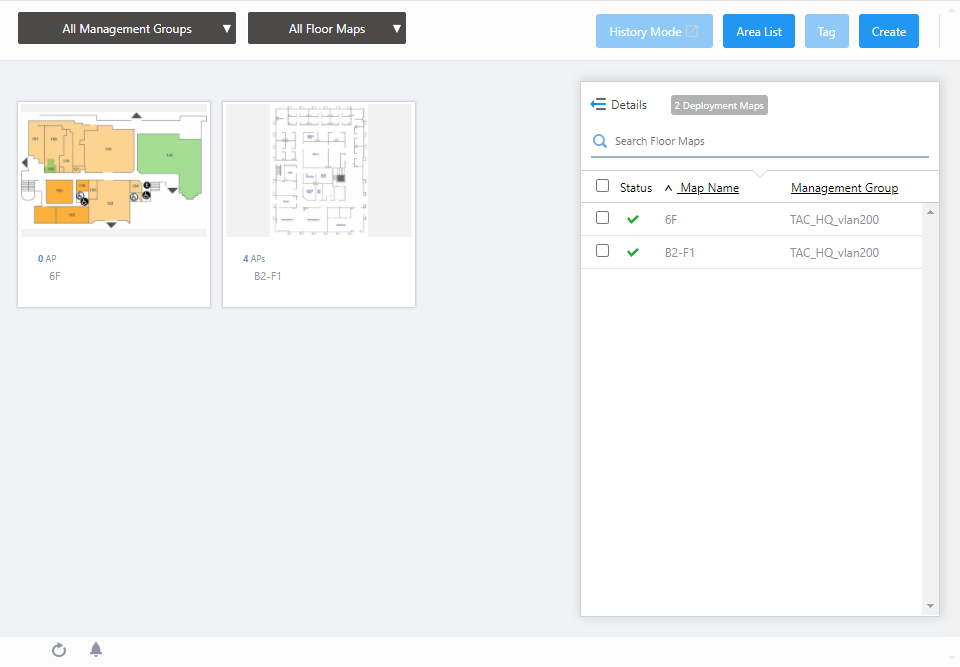
Clicking a floor map panel shows its details.
NoteThe page is periodically refreshed to display the latest information.
NotePlease do not use the automatic scroll feature of your mouse wheel on the page.
NoteLong floor map names may be truncated on the "Floor Map List" in the panel or list view and the "Floor Map Details" page.
To see an entire name, go to the "Floor Map List" > "List View" icon > "Pencil" icon > "Edit Floor Map" page.
NoteIf you sort by IP address, the addresses in an AP list are sorted in lexicographical order.
Floor Map List
Section 1
| Item Name | Description |
|---|---|
| Management group drop-down menu | Narrow down the floor map to be displayed. The default is "All Management Groups". |
| Floor Map drop-down menu |
Select the floor map to be configured. The default is "All Floor Maps". When you select one of the floor maps, the display in the center of the contents section will switch from the floor map list view to the floor map detail view. |
| "History Mode" button |
Displays "History Mode" screen to recall the status of APs and associated clients in the floor map details for a specified period. To use History Mode, the VST-APL on the same subnet must be registered as Vista Appliance Storage. For more information about the History Mode, please refer to Screen Reference > Wireless Monitor > Floor Map History Mode. |
| "Area List" button |
Opens the "All Area List" dialog box.  Lists all the areas created on any floor maps, along with information of Area Authentication VAPs associated with each area.
|
| "Tag" button |
NoteThe "Edit Tags" button cannot be used in Panel View. |
| "Create" button | Opens the "Create Floor Map" dialog box. Refer to Operation Reference > Floor Map > Configure Floor Maps for more details. |
Section 2
| Item Name | Description |
|---|---|
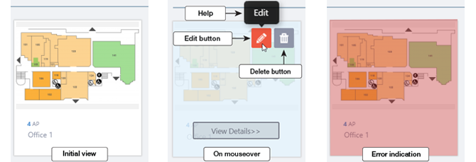
| Floor Map Panels |
Each floor map is shown as a panel. The name of the floor map and the number of APs placed on the map are shown below the panel. When an Admin user hovers over a panel, that panel will become half-opaque, and "Edit" (pencil) and "Delete" (trashbin) buttons will appear at the top right of the panel Clicking the panel opens the "Floor Map Details" page for the floor map.
|
Section 3
| Details | You can click to see the information such as the number of Deployed APs, and Tags, in addition to the default items of Status, Floor Map Name, and Management Group Name. Floor Map Panel will not be displayed in the extended state of Floor Map List. Clicking Details again returns you to the default non-detailed view. |
| X Deployment Map | Shows the number of floor maps. |
| Search Floor Map |
Filter entries in the list by entering a partial string in the search box. The Search field lets you enter a partial string to match. The screen displays entries with that string in one of the following fields: "Floor Map Name", "Management Group Name" or "Tag". To remove the filter, delete the string from the Search field and press Enter. NoteThe search is case-sensitive. |
| Checkbox | Check this box if you want to select the floor map as the display target. |
| Status Icon |
Overall status of the APs on the floor map is indicated by an icon. A green checkmark means everything is normal. A red triangle indicates some APs on the map have an issue. |
| Floor Map Name | Shows the name of the floor map. |
| Management Group | Shows management groups for the floor map. |
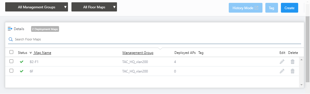
Click the "Detail" button to switch to the expanded view of the Floor Map list.
| Item Name | Description |
|---|---|
| Details | Click to return to the list display of Status, Floor Map Name, and Management Group Name. The Floor Map Panels will also be displayed on the left side of the Contents section. |
| X Deployment Map | Shows the number of floor maps. |
| Search Floor Map |
Filter entries in the list by entering a partial string in the search box. The Search field lets you enter a partial string to match. The screen displays entries with that string in one of the following fields: "Floor Map Name", "Management Group Name" or "Tag". To remove the filter, delete the string from the Search field and press Enter. NoteThe search is case-sensitive. |
| Checkbox | To edit tags for floor maps, use the checkbox to select the maps and click this button. |
| Status Icon |
Overall status of the APs on the floor map is indicated by an icon. A green checkmark means everything is normal. A red triangle indicates some APs on the map have an issue. |
| Floor Map Name | Shows the name of the floor map. |
| Management Group | Shows management groups for the floor map. |
| Deployed APs | Shows the number of wireless APs placed on the floor map. |
| Tag | Shows tags added to the floor map. |
| "Edit" (pencil) button: | Lets you edit the floor map. |
| "Delete" (trashbin) button: | Lets you delete the floor map. |
Detail and Layered Views of Floor Maps
You can select the floor map to be displayed from the management group drop-down menu and Floor Map drop-down menu in the header of the Floor Map list.If you select multiple Floor Maps in the same management group, you can view the layered view of the Floor Maps in 3D.
- Layered Floor Map View
A layered 3D view of the floor map will be displayed in the following case:
- When a specific management group is selected in the management group drop-down menu at the top of the screen, a specific floor map is not selected in the Floor Map drop-down menu, and multiple floor maps are selected in the Floor Map list on the right side of the screen.
The layered floor map view allows you to grasp the status of APs, the number of associated clients and their locations and flow lines (when AWC-CB is used and the Client Location Estimation History function is enabled), and the connections of APs in the AWC-SC configuration across the floor maps in the same management group.
- When a specific management group is selected in the management group drop-down menu at the top of the screen, a specific floor map is not selected in the Floor Map drop-down menu, and multiple floor maps are selected in the Floor Map list on the right side of the screen.
- Floor Map Details
The floor map details will be displayed in the following cases:
- When you select a specific management group in the management group drop-down menu at the top of the screen, and then select a specific floor map with one of the following
- Floor map drop-down menu at the top of the screen
- Floor map panel in the center of the screen
- Floor map drop-down menu at the top of the screen
In the floor map details, you can monitor the status of APs, the number of associated clients, their locations and flow lines (when AWC-CB is used and the Client Location Estimation History function is enabled), and the connections of APs in the AWC-SC configuration, as well as monitor rogue APs detected by each managed AP.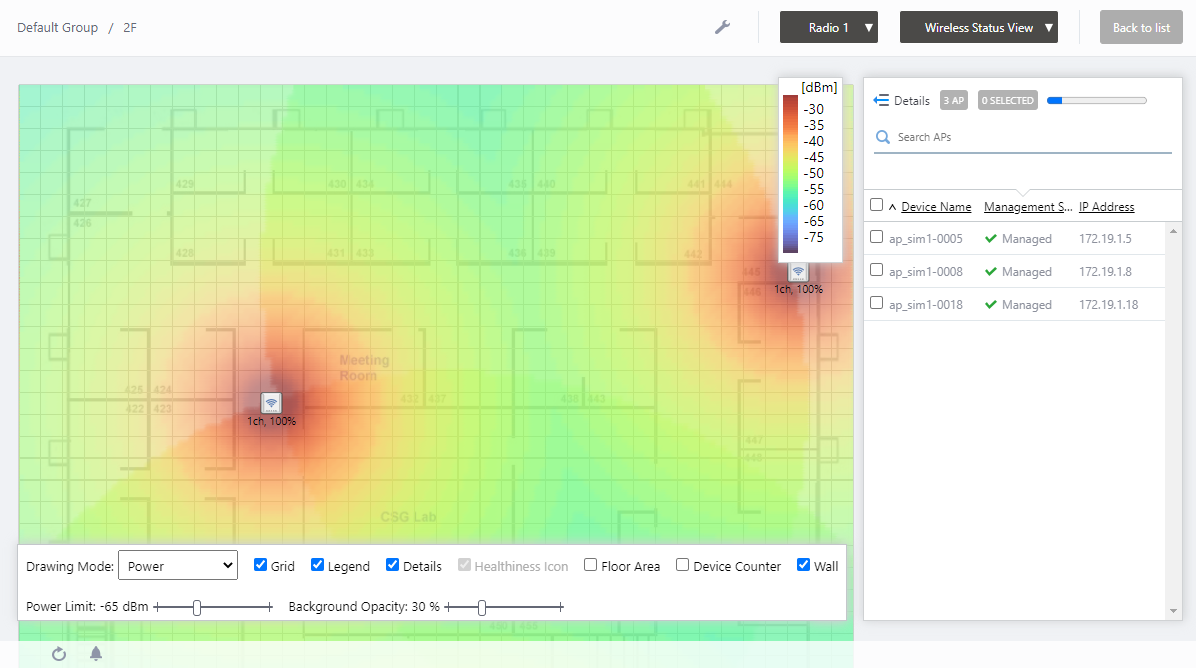
You can also locate APs on the floor map, edit the area, and edit the walls in the floor map detail view.
- When you select a specific management group in the management group drop-down menu at the top of the screen, and then select a specific floor map with one of the following
Layered Floor Maps [Wireless Status View]
To display the layered floor map view, select a specific management group from the management group drop-down menu on the floor map List screen, and then check any floor maps from the Floor Map List on the right.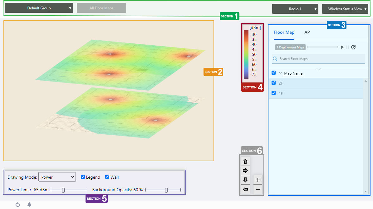
Section 1
| Item Name | Description |
|---|---|
| Management group drop-down menu | Narrow down the floor map to be displayed. If you change the currently selected management group, the Layered Floor Map view will be canceled and you will return to the Floor Map List panel view. |
| Floor Map drop-down menu |
This is not available in the layered floor map view. |
| Radio dropdown menu | Lets you select a radio band to show on the map, from Radio 1, 2 or 3. |
| View Selection dropdown menu |
Lets you change what information is displayed on the Floor Map Details screen.
|
Section 2
The selected floor map will be displayed layer by layer.
The display angle of the floor maps can be controlled using the angle adjustment buttons on the bottom right.
NoteThe order of the stacked floor maps is displayed in ascending order by the character code of the floor map name, starting from the bottom. This cannot be rearranged.
Each floor map displays the icons of the APs placed in the individual floor map detail screen, a heat map showing the channel or signal reach and strength in color around the wireless APs, and the areas or walls you have created.
The drawing mode of the heat map can be selected from the floor map control.
NoteEven between wireless APs operating at the same radio strength, the size of output circle on the heat map may vary depending on the installation location and other factors.
When you place your mouse cursor on an AP, management information of the AP will pop up.
- Wireless AP Name
- MAC Address
- IP Address
Section 3
Floor maps / wireless AP list will be displayed. You can switch between the floor map list and the wireless AP list using the tabs at the top of the list.
Place the mouse pointer on any line in the floor map list to highlight the corresponding floor map in the layered view.
Also, when you place the mouse pointer on any line of the wireless AP list, the corresponding wireless AP icon on the floor map will be highlighted with a blue dot.
| Item Name | Description |
|---|---|
| Header | |
| Floor Map/AP Tab | Switches the contents of the list. |
| Floor Map List | |
| X Deployment Map | Displays the number of floor maps that belong to the selected management group. |
| Refresh Timer |
Shows the status of the timer that automatically refreshes the page with the blue progress bar. The list is automatically refreshed at the interval configured on "Refresh Rates" > "Floor MAP (Wireless Status)" in the User Management menu. (The default is 1 minute.) In the layered floor maps view, the resume/pause automatic update buttons and the manual update button are displayed along with a progress bar. By default, automatic updates are paused. |
| Search Floor Map |
This item is disabled in the layered floor maps. |
| Checkbox | Check this box if you want to select the floor map as the display target. |
| Map Name | The floor map names belonging to the selected management group will be displayed. |
| AP list | |
| X AP | Shows the number of APs placed on the floor map. |
| Refresh Timer |
Shows the status of the timer that automatically refreshes the page with the blue progress bar. The list is automatically refreshed at the interval configured on "Refresh Rates" > "Floor MAP (Wireless Status)" in the User Management menu. (The default is 1 minute.) In the layered floor maps view, the resume/pause automatic update buttons and the manual update button are displayed along with a progress bar. By default, automatic updates are paused. |
| "Search" box |
Filter entries in the list by entering a partial string in the search box. Displays the items among the current display targets that contain the string entered in this field in either " Device Name" or "Floor Map Name". To remove the filter, delete the string from the Search field and press Enter. NoteThe search is case-sensitive. |
| Device Name | Shows the name given to the AP. |
| Map Name | The name of the floor map the AP belongs to is displayed. |
| Management Status | Shows the management status of the AP. |
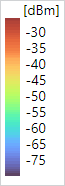
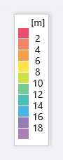
Section 4
It shows the relationship between colors and signal strength or channels.
The legend can be made invisible or visible by using a checkbox in the floor map control section at the bottom of the page.
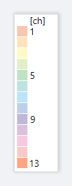
Color conventions depend on the floor map drawing mode.
- Power
- Channel
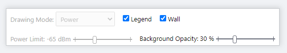
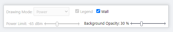
Section 5
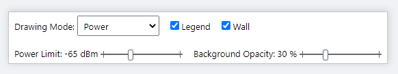
| Item Name | Description |
|---|---|
| Drawing Mode | Lets you select what to show on the heatmap. Options are power (signal strength) and channel. |
| Legend | Lets you enable or disable the legend. Check to display. |
| Wall |
If walls have been created on the floor map (using the Edit Wall page), this lets you choose whether to display the walls. Check to display.NoteIf walls have been defined, attenuation by the walls takes effect on the heat map even when this control is left unchecked. |
| Power Limit | Specify the minimum signal strength to show in colors on the heatmap. |
| Opacity | Specify the opacity of the floor map background image. |
Section 6
Adjusts the display size and angle of the map.
- Zoom In/Out buttons
You can zoom in (+) or zoom out (-) of the floor map display. You can also use the mouse wheel scroll to zoom in or out.

- Angle adjustment buttons
Only in the layered view, the angle at which the floor map is displayed can be adjusted using the arrow buttons.
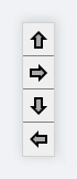
- Up/Down arrows: Adjust the vertical (pitch) angle.
- Left/Right arrows: Adjust the horizontal rotation (yaw) angle.
- Up/Down arrows: Adjust the vertical (pitch) angle.
Layered Floor Maps [Associated Client View]
On the Layered Floor Map view, select "Associated Client View" from the View Selection dropdown menu to display the information of the associated clients on the currently selected floor maps.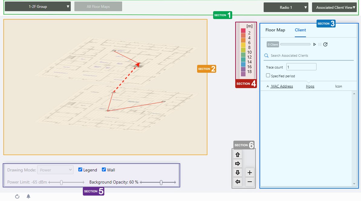
Section 1
| Item Name | Description |
|---|---|
| Management group drop-down menu | Narrow down the floor map to be displayed. If you change the currently selected management group, the Layered Floor Map view will be canceled and you will return to the Floor Map List panel view. |
| Floor Map drop-down menu |
This is not available in the layered floor map view. |
| Radio dropdown menu | Lets you select a radio band to show on the map, from Radio 1, 2 or 3. |
| View Selection dropdown menu |
Lets you change what information is displayed on the Floor Map Details screen.
|
Section 2
The selected floor map will be displayed layer by layer.
The display angle of the floor maps can be controlled using the angle adjustment buttons on the bottom right.
NoteThe order of the stacked floor maps is displayed in ascending order by the character code of the floor map name, starting from the bottom. This cannot be rearranged.
Each floor map displays the icons of the wireless APs you have placed on the individual floor map detail screens.
You can view the estimated location of the selected wireless client in the client list on the right side of the content section. For the estimated location of a wireless client, you can also view the path it has traveled in the recent past or over a specified period.
Section 3
Floor maps / wireless client list will be displayed. You can switch between the floor map list and the wireless client list using the tabs at the top of the list.Place the mouse pointer on any line in the floor map list to highlight the corresponding floor map in the layered view.
| Item Name | Description |
|---|---|
| Header | |
| Floor Map/Client Tab | Switches the contents of the list. |
| Floor Map List | |
| X Deployment Map | Displays the number of floor maps that belong to the selected management group. |
| Refresh Timer |
Shows the status of the timer that automatically refreshes the page with the blue progress bar. In the layered floor maps view, the resume/pause automatic update buttons and the manual update button are displayed along with a progress bar. By default, automatic updates are paused. |
| Search Floor Map |
This item is disabled in the layered floor maps. |
| Checkbox | Check this box if you want to select the floor map as the display target. |
| Map Name | The floor map names belonging to the selected management group will be displayed. |
| Client list | |
| X Client | Displays the number of wireless clients connected to the wireless AP, or the number of wireless clients that have a history of connecting to the wireless AP during the specified period. |
| Refresh Timer |
Shows the status of the timer that automatically refreshes the page with the blue progress bar. In the layered floor maps view, the resume/pause automatic update buttons and the manual update button are displayed along with a progress bar. By default, automatic updates are paused. |
| Search Associated Clients |
You can search for clients that are currently connected to the AP or have a history of connecting to the AP during the specified period. Displays the items among the current display targets that contain the string entered in this field in the "MAC Address" field. To remove the filter, delete the string from the Search field and press Enter. NoteThe search is case-sensitive. |
| Trace count |
Specifies the number of client movement histories to be reflected in the flow lines on the floor map. In the case of wireless clients whose location is estimated by Client Location Estimation, the floor map will reflect the estimated location for the specified number of times from the history of location estimation performed. For wireless clients that do not have client location estimation applied, the floor map will reflect the connection locations for the specified number of times from the roaming history of the connected AP. |
| Specified period |
Check this box if you want to specify a specific period of the location estimation history or connection history to be displayed on the floor maps. When checked, you can specify the start and end date and time of a specified period manully or using the calendar control. Specify the period and click the "Search" button to reflect it in the list. |
| Checkbox | Select a wireless client to display its estimated location or associated wireless APs on the floor map. |
| MAC Address | Shows the MAC address of the wireless client. |
| Hops |
Displays the hop count of the wireless client. For wireless clients whose connection location is estimated by Client Location Estimation, specify the number of times the location estimation is performed for each wireless client on the floor map. Only the specified number of the most recent hops will be displayed for each client. For wireless clients where Client Location Estimation is not applied, the roaming count of the connected wireless AP is displayed. |
| Icon |
Displays the wireless client icon shown on the floor map.
|
Section 4
Shows the legend for the Associated Client View.
The color of each cell in the legend represents the reliability of the location estimation of clients shown on the map.
The legend can be made invisible or visible by using a checkbox in the floor map control section at the bottom of the page.
Section 5
| Item Name | Description |
|---|---|
| Legend | Lets you enable or disable the legend. Check to display. |
| Wall |
If walls have been created on the floor map (using the Edit Wall page), this lets you choose whether to display the walls. Check to display.NoteIf walls have been defined, attenuation by the walls takes effect on the heat map even when this control is left unchecked. |
| Opacity | Specify the opacity of the floor map background image. |
Section 6
Adjusts the display size and angle of the map.
- Zoom In/Out buttons
You can zoom in (+) or zoom out (-) of the floor map display. You can also use the mouse wheel scroll to zoom in or out.
- Angle adjustment buttons
Only in the layered view, the angle at which the floor map is displayed can be adjusted using the arrow buttons.
- Up/Down arrows: Adjust the vertical (pitch) angle.
- Left/Right arrows: Adjust the horizontal rotation (yaw) angle.
- Up/Down arrows: Adjust the vertical (pitch) angle.
Layered Floor Maps [Smart Connect View]
On the Layered Floor Map view, select "Smart Connect View" from the View Selection dropdown menu to display the information of the Smart Connect on the currently selected floor maps.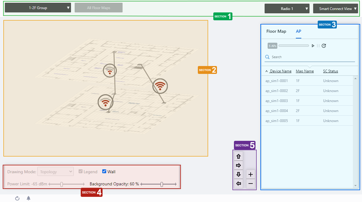
Section 1
| Item Name | Description |
|---|---|
| Management group drop-down menu | Narrow down the floor map to be displayed. If you change the currently selected management group, the Layered Floor Map view will be canceled and you will return to the Floor Map List panel view. |
| Floor Map drop-down menu |
This is not available in the layered floor map view. |
| Radio dropdown menu | Lets you select a radio band to show on the map, from Radio 1, 2 or 3. |
| View Selection dropdown menu |
Lets you change what information is displayed on the Floor Map Details screen.
|
Section 2
The selected floor map will be displayed layer by layer.
The display angle of the floor maps can be controlled using the angle adjustment buttons on the bottom right.
NoteThe order of the stacked floor maps is displayed in ascending order by the character code of the floor map name, starting from the bottom. This cannot be rearranged.
Each floor map shows the icons of the APs placed and the walls created in the individual floor map detail view. When the APs are wirelessly connected by AWC-SC, the connection status between the APs is indicated by a gray link line and a healthiness icon.
The healthiness icon indicates the strength of the signal between APs by the number of ripples in the icon.
![]()
| Number of bars | Power | |
|---|---|---|
| 4 | -57dBm or greater | |
| 3 | -62 to -58dBm | |
| 2 | -69 to -63dBm | |
| 1 | -79 to -70dBm | |
| 0 | -80dBm or less | |
When you place your mouse cursor on an AP, management information of the AP will pop up.
- Wireless AP Name
- MAC Address
- IP Address
Section 3
Floor maps / wireless AP list will be displayed. You can switch between the floor map list and the wireless AP list using the tabs at the top of the list.Place the mouse pointer on any line in the floor map list to highlight the corresponding floor map in the layered view.
Also, when you place the mouse pointer on any line of the wireless AP list, the corresponding wireless AP icon on the floor map will be highlighted with a blue dot.
| Item Name | Description |
|---|---|
| Header | |
| Floor Map/AP Tab | Switches the contents of the list. |
| Floor Map List | |
| X Deployment Map | Displays the number of floor maps that belong to the selected management group. |
| Refresh Timer |
Shows the status of the timer that automatically refreshes the page with the blue progress bar. In the layered floor maps view, the resume/pause automatic update buttons and the manual update button are displayed along with a progress bar. By default, automatic updates are paused. |
| Search Floor Map |
This item is disabled in the layered floor maps. |
| Checkbox | Check this box if you want to select the floor map as the display target. |
| Map Name | The floor map names belonging to the selected management group will be displayed. |
| AP list | |
| X AP | Shows the number of APs placed on the floor map. |
| Refresh Timer |
Shows the status of the timer that automatically refreshes the page with the blue progress bar. In the layered floor maps view, the resume/pause automatic update buttons and the manual update button are displayed along with a progress bar. By default, automatic updates are paused. |
| "Search" box |
Filter entries in the list by entering a partial string in the search box. Displays the items among the current display targets that contain the string entered in this field in either " Device Name" or "Floor Map Name". To remove the filter, delete the string from the Search field and press Enter. NoteThe search is case-sensitive. |
| Device Name | Shows the name given to the AP. |
| Map Name | The name of the floor map the AP belongs to is displayed. |
| SC Status |
Shows the AP's role in AWC-SC.
|
Section 4
| Item Name | Description |
|---|---|
| Wall |
If walls have been created on the floor map (using the Edit Wall page), this lets you choose whether to display the walls. Check to display.NoteIf walls have been defined, attenuation by the walls takes effect on the heat map even when this control is left unchecked. |
| Opacity | Specify the opacity of the floor map background image. |
Section 5
Adjusts the display size and angle of the map.
- Zoom In/Out buttons
You can zoom in (+) or zoom out (-) of the floor map display. You can also use the mouse wheel scroll to zoom in or out.
- Angle adjustment buttons
Only in the layered view, the angle at which the floor map is displayed can be adjusted using the arrow buttons.
- Up/Down arrows: Adjust the vertical (pitch) angle.
- Left/Right arrows: Adjust the horizontal rotation (yaw) angle.
- Up/Down arrows: Adjust the vertical (pitch) angle.
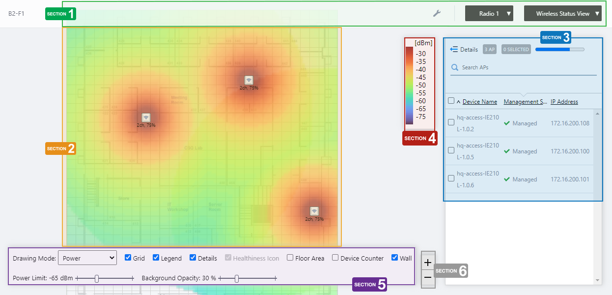
Floor Map [Wireless Status View]
Clicking on a floor map panel or selecting a specific floor map from the floor map dropdown menu will show the "Floor Map Details" page.The floor map is displayed in the center of the Content section and a list of APs is shown on the right side of the Content section.
NoteThe status displayed for an unreachable AP is the status that was last collected.
NoteIf you try to move an AP icon, it may move to an unintended position and your mouse cursor and the icon may become out of sync.
If this occurs, release your mouse button and drag the icon again.
NoteIf you try to place an AP on a floor map that was deleted by another user, you will be brought back to the "Floor Map Details" page without any error message. In such cases, please check if the floor map still exists on the "Floor Map List" page.
Section 1
| Item Name | Description |
|---|---|
| Management Group / Floor Map Group | The floor map name and the management group of the selected floor map will be displayed. |
| "Spanner" icon |
Hovering the mouse cursor over the Spanner icon shows a dropdown menu including some operations for managed APs. Select APs by checking on the AP list or clicking the AP icons on the floormap, you can then execute the following operation for the selected APs.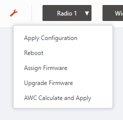
|
| Radio dropdown menu | Lets you select a radio band to show on the map, from Radio 1, 2 or 3. |
| View Selection dropdown menu |
Lets you change what information is displayed on the Floor Map Details screen.
|
| "Back to list" button | Click to return to the Floor Map List screen. |
Section 2
| Item Name | Description |
|---|---|
| Floor Map (Background) | The map image specified when you created the map is shown. You can place icons for the APs in the righthand-side list. |
| Wireless AP Icon |
AP icons placed on the map is shown. Below each icon, the channel and transmit power for the AP are displayed. Notes on icons:
|
Section 3
| Item Name | Description |
|---|---|
| Details | Clicking this shows the device's model, MAC address, AP Profile, the number of associated clients for each radio, and tags, as well as the Device name, Management Status and IP address that are shown on the non-detailed view. Clicking Details again returns you to the default non-detailed view. |
| X AP | Shows the number of APs placed on the floor map. |
| Refresh Timer | Shows the status of the timer that automatically refreshes the page with the blue progress bar. The list is automatically refreshed at the interval configured on "Refresh Rates" > "Floor MAP (Wireless Status)" in the User Management menu. (The default is 1 minute.) |
| Search Wireless AP |
Filter entries in the list by entering a partial string in the search box. The Search field lets you enter a partial string to match. The screen displays entries with that string in one of the following fields: "Device Name", "Management Status", "IP address", "MAC address" or "AP Profile" fields. To remove the filter, delete the string from the Search field and press Enter. NoteThe search is case-sensitive. |
| Filter by tag |
Lets you filter APs with tags. Clicking tags uses tags to filter the list. Clicking them again removes the filter. Clicking "Clear filter" removes the filter for all tags. NoteTo select tags, you have to switch the list to detailed mode (by clicking "View Details"). |
| Tag | All tags are displayed under the "Search Wireless AP" box. |
| Status Icon | When the AP is managed by the AWC Plug-in, a green checkmark is displayed. When the AP is not managed by the AWC Plug-in, a red triangle is displayed. |
| Device Name | Shows the name given to the AP. |
| Management Status | Shows the management status of the AP. |
| IP Address | Shows the AP's IP address. |
Section 4
Shows the heatmap legend.
It shows the relationship between colors and signal strength or channels.
The legend can be made invisible or visible by using a checkbox in the floor map control section at the bottom of the page.
Color conventions depend on the floor map drawing mode.
- Power
- Channel
Section 5
In Wireless Status View, the "Healthiness Icon" is disabled.

| Item Name | Description |
|---|---|
| Drawing Mode | Lets you select what to show on the heatmap. Options are power (signal strength) and channel. |
| Grid | Lets you enable or disable grid lines on the floor map. Checking this shows grid lines on the floor map. |
| Legend | Lets you enable or disable the legend. Check to display. |
| Details | Check to display the list of placed APs. Check to display. |
| Floor Area | If areas have been created on the floor map (using the Edit Area page), lets you choose whether to display the areas. Check to display. |
| Device Counter | On the top left of an area, indicates the number of registered APs that are arranged in the area. |
| Wall |
If walls have been created on the floor map (using the Edit Wall page), this lets you choose whether to display the walls. Check to display.NoteIf walls have been defined, attenuation by the walls takes effect on the heat map even when this control is left unchecked. |
| Power Limit | Specify the minimum signal strength to show in colors on the heatmap. |
| Opacity | Specify the opacity of the floor map background image. |
Section 6
Zoom In/Out buttons.
You can zoom in (+) or zoom out (-) of the floor map display. You can also use the mouse wheel scroll to zoom in or out.
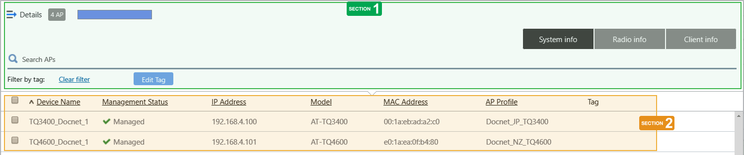
Arranged AP List (Detail)
Clicking "Details" at the top of the list of placed APs on the "Floor Map Details" page extends the list to show additional information such as Device Type and AP Profile.Information displayed on the list can be switched between "System info", "Radio info" and "Client info". By default, each AP's system information is displayed.
Section 1
| Item Name | Description |
|---|---|
| Details | Clicking "Details" again on the extended list shrinks the list to its default size. |
| X AP | Shows the number of wireless APs placed on the floor map. |
| Refresh Timer | Shows the status of the timer that automatically refreshes the page with the blue progress bar. The list is automatically refreshed at the interval configured on "Refresh Rates" > "Floor MAP (Wireless Status)" in the User Management menu. (The default is 1 minute.) |
| Search Wireless AP |
The Search field lets you enter a partial string to match. The screen displays entries with that string in one of the following fields: "Device Name", "Management Status", "IP address", "MAC address" or "AP Profile" fields. To remove the filter, delete the string from the Search field and press Enter. NoteThe search is case-sensitive. |
| "System Information" button | Switches the list content to system information for the APs placed on the floor map. |
| "Wireless Information" button | Switches the list content to the wireless configuration of the APs placed on the floor map. |
| "Client Info" button | Switches the list content to the number of clients (per radio) connected to each AP placed on the floor map. |
| Filter by tag |
Lets you filter APs with tags. Clicking tags uses tags to filter the list. Clicking them again removes the filter. Clicking "Clear filter" removes the filter for all tags. |
| Tag | All tags are displayed under the "Search Wireless AP" box. |
| "Tag" button |
Lets you edit tags for the selected APs. To add the same tags to the APs and the floor map, check "Add the same tags to the floor map". NoteIf you paste a tag string from the clipboard, not all text may be visible. In that case, press Enter to make a tag from the entire pasted string. NotePasting a tag containing a newline is not supported. NoteTag names may be truncated in the tag filter list on the Devices Map, Floor Map Details and Device Search pages. To avoid this, use shorter names for the tags.
|
Section 2
| Item Name | Description |
|---|---|
| System Info | |
| Checkbox | To edit tags for APs, use the checkboxes to select APs and then click the "Edit Tags" button. |
| Device Name | Shows the name given to the AP. |
| Management Status | Shows the management status of the AP. |
| IP Address | Shows the AP's IP address. |
| Model | Shows the model name of the AP. |
| MAC Address | Shows the device's MAC address. |
| AP Profile | Shows the AP Profile assigned to the AP. |
| Tag | Shows the tags set on the AP. |
| Radio info | |
| Device Name | Shows the name given to the AP. |
| Channel (Radio1) Channel (Radio2) Channel (Radio3) |
Shows the channel used on each radio band of the AP. |
| Tx Power (Radio1) Tx Power (Radio2) Tx Power (Radio3) |
Shows the transmit power for each radio band of the AP. |
| Client info | |
| Device Name | Shows the name given to the AP. |
| Associated Clients (Radio 1) Associated Clients (Radio 2) Associated Clients (Radio 3) |
Shows the number of clients (per radio band) connected to the AP. |
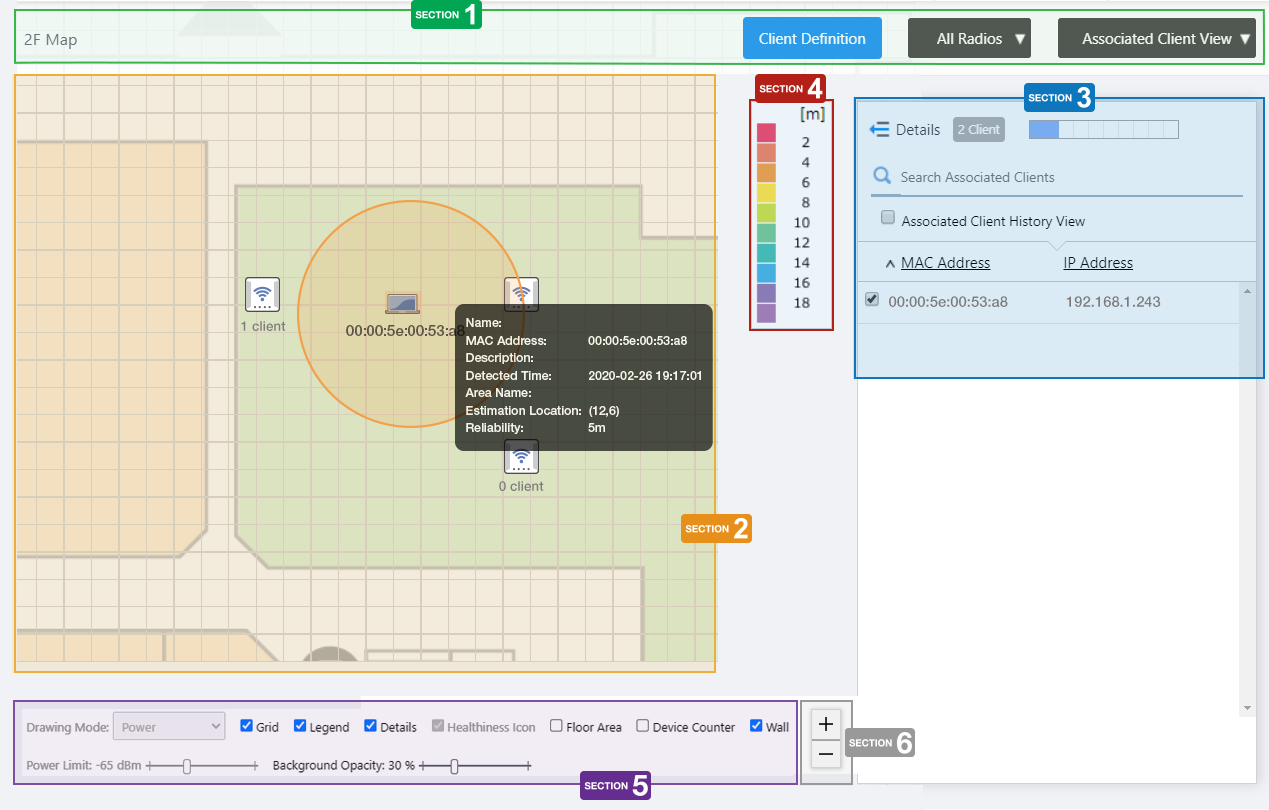
Floor Map [Associated Client View]
If you select "Associated Client View" from the dropdown menu on Floor Map Details, the screen switches to the Associated Client View screen.If AWC was able to estimate the location of the associated clients, then this view shows the clients' estimated locations on the Floor Map. This is called the Associated Client Location Estimation display. If AWC was not able to estimate the location of the associated clients, then this view shows the clients arranged near their associated AP, to show affiliation. This is called the Client Association View display. These display optiions may be mixed, so that the Associated Client View screen shows a mix of location estimation and affiliation display for connected clients.
Client Location Estimation View
The position estimated from the radio wave of the associated client detected by the AP is reflected in the coordinates on the Floor Map and displayed.This can occur when all of the following conditions are met:
- The wireless client has connected to a Channel Blanket VAP.
- "Client Location Estimation History" is enabled in System Settings.
- Location information is calculated by the Associated Client Location Estimation function.
NoteClient Location Estimation is available on this version of the AWC Plug-in combined with AT-TQ5403/5403e firmware version 6.0.1-1.x or later.
NoteWhen using the Client Location Estimation View, set the floor map dimensions (vertical / horizontal) correctly and match AP placement with the actual environment.
NoteSystem clocks on all the managed APs and the server running the AWC Plug-in must be synchronized.
NoteThis feature is available when the Retention Period for "Client Location Estimation History" in System Settings is set. If this feature is enabled, the maximum number of wireless APs that can have CB Profiles applied is 500 across the entire system.
Section 1
| Item Name | Description |
|---|---|
| Management Group / Floor Map Group | The floor map name and the management group of the selected floor map will be displayed. |
| "Client Definition" button | Shows the Client Definition List dialog box. |
| Radio dropdown menu | Select which radio band information to display from Radio 1, Radio 2, Radio 3, or "All Radios". The default is "All Radios". If you select "All Radios", Associated Client Information for all bands (Radio 1, Radio 2, and Radio 3) will be displayed. |
| View Selection dropdown menu |
Lets you change what information is displayed on the Floor Map Details screen.
|
| Floor Map (Background) | The map image specified when you created the map is shown. |
| Wireless AP Icon |
The AP icon placed on the floor map is displayed. Below the icon, the number of associated clients is displayed. When you click an AP icon, only clients connected to the AP are displayed in the associated client list. |
| "Back to list" button | Click to return to the Floor Map List screen. |
Section 2
| Item Name | Description |
|---|---|
| Wireless Client icon |
Shows the wireless clients that have been connected to the AP on the map. Each estimated location is represented by a client icon.
You can click the Associated Client icon to see the probable circle of location based on the estimation reliability. You can also hover over the Associated Client icon to see popup information about the estimated client. |
Section 3
| Item Name | Description |
|---|---|
| Details | You can click here to see client details such as Hostname, Username (based on WPA Enterprise), Duration, Client Name, Notes, SSID, Associating AP, and RSSI, in addition to the items displayed by default (MAC and IP addresses). Clicking Details again returns you to the default non-detailed view. |
| X Client | Shows the number of clients connected to the AP that is selected on the floor map. |
| Refresh Timer | Shows the status of the timer that automatically refreshes the page with the blue progress bar. The list is automatically refreshed at the interval configured on "Refresh Rates" > "Floor MAP (Associated Client)" in the User Management menu. (The default is 5 seconds.) |
| Search Associated Clients |
Filter entries in the list by entering a partial string in the search box. The Search field lets you enter a partial string to match. The screen displays entries with that string in one of the following fields: "MAC Address", "IP Address", "SSID" or "Associating AP". To remove the filter, delete the string from the Search field and press Enter. NoteThe search is case-sensitive. |
| "Show Client History" checkbox | Switches the page to Associated Client History. |
| Checkbox |
Lets you select wireless clients to be shown on the floor map. When you select a client, an icon and the MAC address of the client are shown near the AP with which the client is associated. |
| MAC Address | Shows the MAC address of the wireless client. |
| IP Address | Shows the IP address of the wireless client. |
| Icon |
Displays the wireless client icon shown on the floor map.
|
Section 4
Shows the legend for the Associated Client View.
The color of each cell in the legend represents the reliability of the location estimation of clients shown on the map.
The legend can be made invisible or visible by using a checkbox in the floor map control section at the bottom of the page.
Section 5
In the Associated Client Location Estimation View, "Drawing Mode", "Healthiness Icon", and "Power Limit" are irrelevant and disabled.

| Item Name | Description |
|---|---|
| Grid | Lets you enable or disable grid lines on the floor map. Checking this shows grid lines on the floor map. |
| Legend | Lets you enable or disable the legend. Check to display. |
| Details | Whether to display the Associated Client List. Check to display. |
| Floor Area | If areas have been created on the floor map (using the Edit Area page), lets you choose whether to display the areas. Check to display. |
| Device Counter | In the top left of the area on the floor map, indicates the number of associated clients in the area. When "Client Location Estimation History" is enabled in System Settings, this displays the number of clients associated to the APs in the area, the number of associated clients estimated to be in the area, and the number of detected (not associated) clients estimated to be in the area. |
| Wall | If walls have been created on the floor map (using the Edit Wall page), this lets you choose whether to display the walls. Check to display. |
| Opacity | Specify the opacity of the floor map background image. |
Section 6
Zoom In/Out buttons.
You can zoom in (+) or zoom out (-) of the floor map display. You can also use the mouse wheel scroll to zoom in or out.
Associated Client Count
In Associated Client View, when Floor Area and Device Counter on the floor map control are checked, the areas on the map show additional information. The number of clients associated to the APs in the area, as well as the number of associated and detected clients estimated to be in the area, are displayed in the device counter in the top left of the area.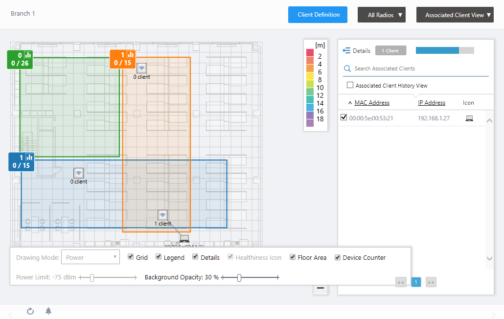
The device counter displays the following.
NoteAssociated/detected client estimation requires Client Location Estimation History in System Setting to be enabled, and also requires channel blanket operating on the APs on the floor map.

- X: Associated Clients
Displays the number of clients in this area.
The total number of wireless clients associated to APs in the area is displayed.
- Y: Associated Client Estimation
Displays the number of clients that are associated to the channel blanket, and estimated to be in the area by the Client Location Estimation feature.
- Z: Detected Client Estimation
Displays the number of clients that are detected and not associated to the channel blanket, and estimated to be in the area by the Client Location Estimation feature.
Note
Detected client estimation only counts the clients that have requested association to the channel blanket VAP provided by the managed APs; that is, the clients that have sent probe requests to the channel blanket SSID. Clients that have never requested association to the channel blanket VAP of the managed APs will not be counted.
When you click on the device counter, the "Area Client History" dialog box will appear.
Area Client History
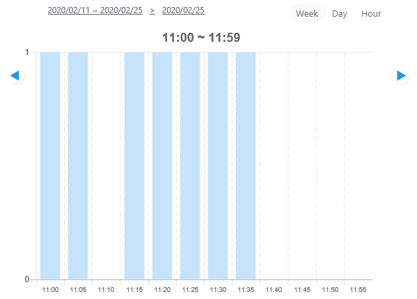
When you click on the device counter of an area in the Associated Client View, the "Area Client History" dialog box will be displayed.You can see graphs of the number of estimated associated or detected clients over a period of two weeks, one day, or one hour. You can also see a list of recorded times of association or detection on a per client basis.
Note◼ Associated ClientClients associated or detected after displaying the "Area Client History" dialog box will not be shown in the counts. For a current count, close the dialog box and then display it again.
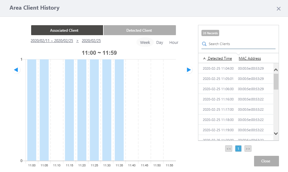
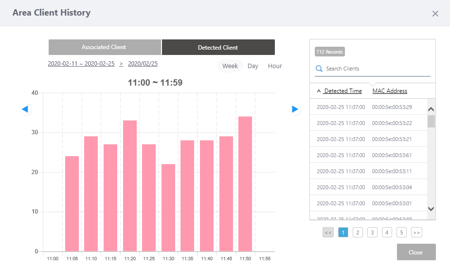
| Associated Client/Detected Client button |
Displays the current mode in dark gray. Click on the other button in light gray to change the mode.
|
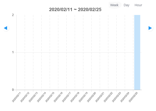
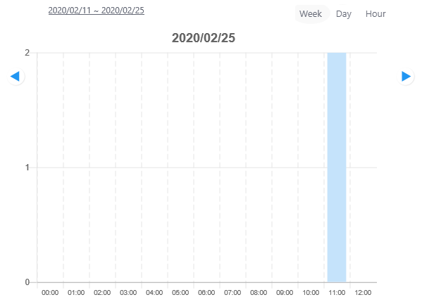
| Display period |
The current display period is shown above the graph, in YYYY/MM/DD ~ YYYY/MM/DD format for two-week, YYYY/MM/DD format for daily, or hh:mm ~ hh:mm format for hourly graph. The top right of the graph indicates the display periods as Week, Day, and Hour. The present period label is displayed with a light gray oval underlay. Also, when displaying a short-term (1 day or 1 hour) graph, a link to the long-term (2 weeks, 1 day) chart is displayed at the upper left of the graph. |
| Graph |
Displays a bar chart that shows the change in number of associated/detected clients in the area over the selected display period. The interval of the bar graphs depends on the display period:
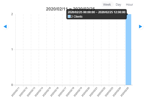 In addition, arrow heads on both sides of the chart let you switch the contents to the next or previous period. |
| Client detection history list |
Displays the MAC addresses and the detected times of the clients estimated to be in the area within the period by the Client Location Estimation feature. Client detection is performed periodically, and when the same MAC address is detected more than once, a detection is recorded each time.
|
| "Exit" button | Closes the "Area Client History" dialog box and goes back to "Floor Map Details [Associated Client View]". |
Client Association View
This view uses a link line to show an association between a client and an AP.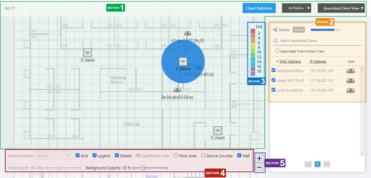
Section 1
| Item Name | Description |
|---|---|
| Floor Map Name | Shows the floor map name. |
| "Client Definition" button | Shows the Client Definition List dialog box. |
| Radio dropdown menu | Select which radio band information to display from Radio 1, Radio 2, Radio 3, or "All Radios". The default is "All Radios". If you select "All Radios", Associated Client Information for all bands (Radio 1, Radio 2, and Radio 3) will be displayed. |
| View Selection dropdown menu |
Lets you change what information is displayed on the Floor Map Details screen.
|
| Floor Map (Background) | The map image specified when you created the map is shown. |
| Wireless AP Icon |
The AP icon placed on the floor map is displayed. Below the icon, the number of associated clients is displayed. When you click an AP icon, only clients connected to the AP are displayed in the associated client list. |
| Wireless Client icon |
An icon representing an associated client. Clients checked on the list will be displayed on the floor map. The position the Client icon is displayed does not indicate the client's actual geographical location on the floor.
|
Section 2
| Item Name | Description |
|---|---|
| Details | You can click here to see client details such as Hostname, Username (based on WPA Enterprise), Duration, Client Name, Notes, SSID, Associating AP, and RSSI, in addition to the items displayed by default (MAC and IP addresses). Clicking Details again returns you to the default non-detailed view. |
| X Client | Shows the number of clients connected to the AP that is selected on the floor map. |
| Refresh Timer | Shows the status of the timer that automatically refreshes the page with the blue progress bar. The list is automatically refreshed at the interval configured on "Refresh Rates" > "Floor MAP (Associated Client)" in the User Management menu. (The default is 5 seconds.) |
| Search Associated Clients |
Filter entries in the list by entering a partial string in the search box. The Search field lets you enter a partial string to match. The screen displays entries with that string in one of the following fields: "MAC Address", "IP Address", "SSID" or "Associating AP". To remove the filter, delete the string from the Search field and press Enter. NoteThe search is case-sensitive. |
| "Show Client History" checkbox | Switches the page to Associated Client History. |
| Checkbox |
Lets you select wireless clients to be shown on the floor map. When you select a client, an icon and the MAC address of the client are shown near the AP with which the client is associated. |
| MAC Address | Shows the MAC address of the wireless client. |
| IP Address | Shows the IP address of the wireless client. |
| Icon |
Displays the wireless client icon shown on the floor map.
|
Section 3
Shows the legend for the Associated Client View.
The color of each cell in the legend represents the reliability of the location estimation of clients shown on the map.
The legend can be made invisible or visible by using a checkbox in the floor map control section at the bottom of the page.
Section 4
In the Client Association View, "Drawing Mode", "Healthiness Icon", and "Power Limit" are irrelevant and disabled.
| Item Name | Description |
|---|---|
| Grid | Lets you enable or disable grid lines on the floor map. Checking this shows grid lines on the floor map. |
| Legend | Lets you enable or disable the legend. Check to display. |
| Details | Whether to display the Associated Client List. Check to display. |
| Floor Area | If areas have been created on the floor map (using the Edit Area page), lets you choose whether to display the areas. Check to display. |
| Wall | If walls have been created on the floor map (using the Edit Wall page), this lets you choose whether to display the walls. Check to display. |
| Opacity | Specify the opacity of the floor map background image. |
Section 5
Zoom In/Out buttons.
You can zoom in (+) or zoom out (-) of the floor map display. You can also use the mouse wheel scroll to zoom in or out.
Associated Client List (Detail)
Clicking "Details" at the top of the client list in the "Associated Client View" extends the list to show additional information including system information, wireless information and statistics.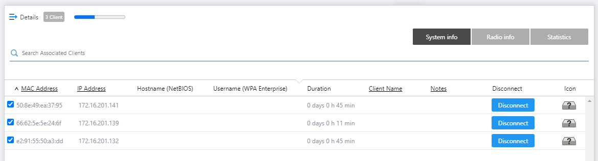
| Item Name | Description |
|---|---|
| Details | Clicking this shows extra data, including the SSID, Associated AP and connection Duration, in addition to the default items (IP and MAC addresses). Clicking Details again returns you to the default non-detailed view. |
| X Client | Shows the number of clients connected to the AP that is selected on the floor map. |
| Refresh Timer | Shows the status of the timer that automatically refreshes the page with the blue progress bar. The list is automatically refreshed at the interval configured on "Refresh Rates" > "Floor MAP (Associated Client)" in the User Management menu. (The default is 5 seconds.) |
| Search Associated Clients |
Filter entries in the list by entering a partial string in the search box. The Search field lets you enter a partial string to match. The screen displays entries with that string in one of the following fields: "MAC Address", "IP Address", "SSID" or "Associating AP". To remove the filter, delete the string from the Search field and press Enter. NoteThe search is case-sensitive. |
| "System Info" / "Wireless Info" / "Statistics" buttons | Switches the contents of the list. |
| System Info | |
| Checkbox |
Lets you select wireless clients to be shown on the floor map. When you select a client, an icon and the MAC address of the client are shown near the AP with which the client is associated. A selection made through the detailed list view will remain when you go back to default (simpler) client list view. |
| MAC Address | Shows the MAC address of the wireless client. |
| IP Address | Shows the IP address of the wireless client. |
| Hostname (NetBIOS) | Shows the NetBIOS host name of the wireless client. |
| Username (WPA Enterprise) | Shows the RADIUS username when using WPA Enterprise. |
| Duration |
Shows the time duration for which the client has been connected to the AP.NoteMake sure that the clock on the computer for browsing is set to the same date and time as the Vista Manager EX server settings. If a different time is set, the duration of wireless clients may not be displayed correctly. |
| Client Name | Shows the Client Name if defined in the "Client Definition List" dialog box. |
| Notes | Shows any comments entered in the "Client Definition List" dialog box. |
| Disconnect |
Disassociates the wireless client connection. If the AP which the client is associated to supports instant disassociation, the "Disconnect" button will be shown. By clicking "Disconnect", you can immediately kick out the wireless client. NoteYou cannot select and disconnect multiple clients simultaneously. Please click the "Disconnect" button of each client. NoteThe feature is supported with TQ5403, TQ5403e, and TQm5403 firmware version 6.0.1-1.x or later; with TQ1402 and TQm1402 firmware version 6.0.0-0.x or later; or TQ6602 firmware version 7.0.0 or later. NoteIf the client device is set to connect automatically to the SSID, the client will be associated soon again after the disassociation. If you want to deny a specific client device permanently, consider using another authentication method such as MAC Access Control. |
| Icon |
Displays the wireless client icon shown on the floor map.
|
| Radio info | |
| MAC Address | Shows the MAC address of the wireless client. |
| SSID | Shows the SSID the client is associated with. |
| Associating AP | Shows the device name of the AP the client is associated with. |
| RSSI | Shows the RSSI (Received Signal Strength Indicator) of the wireless client. |
| Noise | Shows the strength of the noise that is interfering with the client communication. |
| SNR | Shows the Signal to Noise Ratio. A larger SNR means there is less noise influence. |
| Statistics | |
| MAC Address | Shows the MAC address of the wireless client. |
| Tx Packets | Shows the number of the packets sent to the client. |
| Tx Bytes | Shows the total size of the packets sent to the client. |
| Tx Drop Packets | Shows the number of discarded packets to be sent to the client. |
| Tx Drop Bytes | Shows the number of discarded bytes to be sent to the client. |
| Rx Packets | Shows the number of the packets received from the client. |
| Rx Bytes | Shows the total size of the packets received from the client. |
| Rx Drop Packets | Shows the number of received packets which were discarded. |
| Rx Drop Bytes | Shows the number of received bytes which were discarded. |
Note"Noise Level", "SNR", "Transmit Packets Discarded", "Transmit Bytes Discarded", "Received Packets Discarded" and "Received Bytes Discarded" are not supported in this version.
Client Definition List
With this list, you can define display names and notes for specific clients to help with identification in the Associated Client View.The client names will be used only in the Associated Client View and Associated Client History View. The IDS/IPS Report and Management Log screens will not be affected.
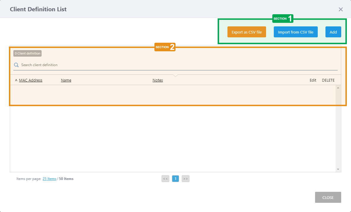
Section 1
| Item Name | Description |
|---|---|
| "Export as CSV file" button | Exports registered client definition to a CSV (Comma-Separated Values) format file. |
| "Import from CSV file" button |
The "Import from CSV" dialog box will appear.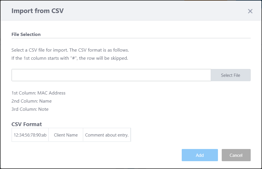
|
| "Add" button |
Shows the "Add client definition" dialog box.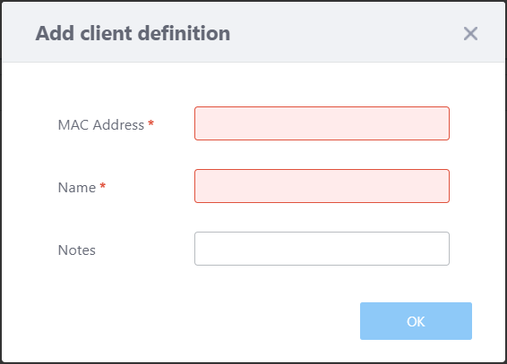
|
Section 2
| Item Name | Description |
|---|---|
| X Client definition | Shows the total number of client definition entries. |
| Search client definition |
Lets you search client definition entries. The Search field lets you enter a partial string to match. The screen displays entries with that string in one of the following fields: "MAC Address", "Name" or "Notes". To remove the filter, delete the string from the Search field and press Enter. NoteThe search is case-sensitive. |
| MAC Address | Shows the defined MAC address. |
| Client Name | Shows the defined display name of the client. |
| Notes | Shows any comments you entered about the client definition. |
| Edit (pencil icon) |
Shows the "Add client definition" dialog box.
|
| Delete (trashbin icon) | Deletes the client definition. |
Associated Client History View
In the Associated Client View, by checking "Associated Client History View", you can view only clients that were associated with the APs on the floor map during the specified time period.If the associated client has an estimated location history, the client is displayed using Client Location Estimation History described below. If AWC does not have past estimates of an associated client's location, then this view shows the Associated Client Roaming History. These display options may be mixed, so that the screen shows a mix of location estimation and roaming for connected clients.
NoteWhen you use Associated Client History with the following wireless APs, please set the log severity of the wireless AP to "information(6)" or higher. If the log severity is set to "debug(7)", this feature is not supported.
The default value of the log severity of these wireless APs is "information(6)". If the wireless APs are not configured for logging, this function can still operate.
Affected wireless APs: TQ1402/5403/5403e/6602, TQm1402/5403
The log severity can be set in the severity of the Syslog client in the AP profile.
If you want to use the Associated Client History View with the log function of the Syslog Client disabled, please change "Syslog Client" to "Enable" and "Severity" to "6 : informational" in the AP profile (the Syslog server IP address/host name can be a fictitious address), apply this AP common setting to the wireless AP, and then set "Syslog Client" to "Disable" in the AP profile and apply it again.
Client Location Estimation History
The position is estimated every minute from the radio of the associated client and displayed.This display appears when all of the following conditions are met in the time period specified:
- The wireless client has connected to a Channel Blanket VAP.
- "Client Location Estimation History" is enabled in System Settings.
- Location information is calculated at least once by Associated Client Location Estimation.
NoteWhen using the Client Location Estimation View, set the floor map dimensions (vertical / horizontal) correctly and match AP placement with the actual environment.
NoteSystem clocks on all the managed APs and the server running the AWC Plug-in must be synchronized.
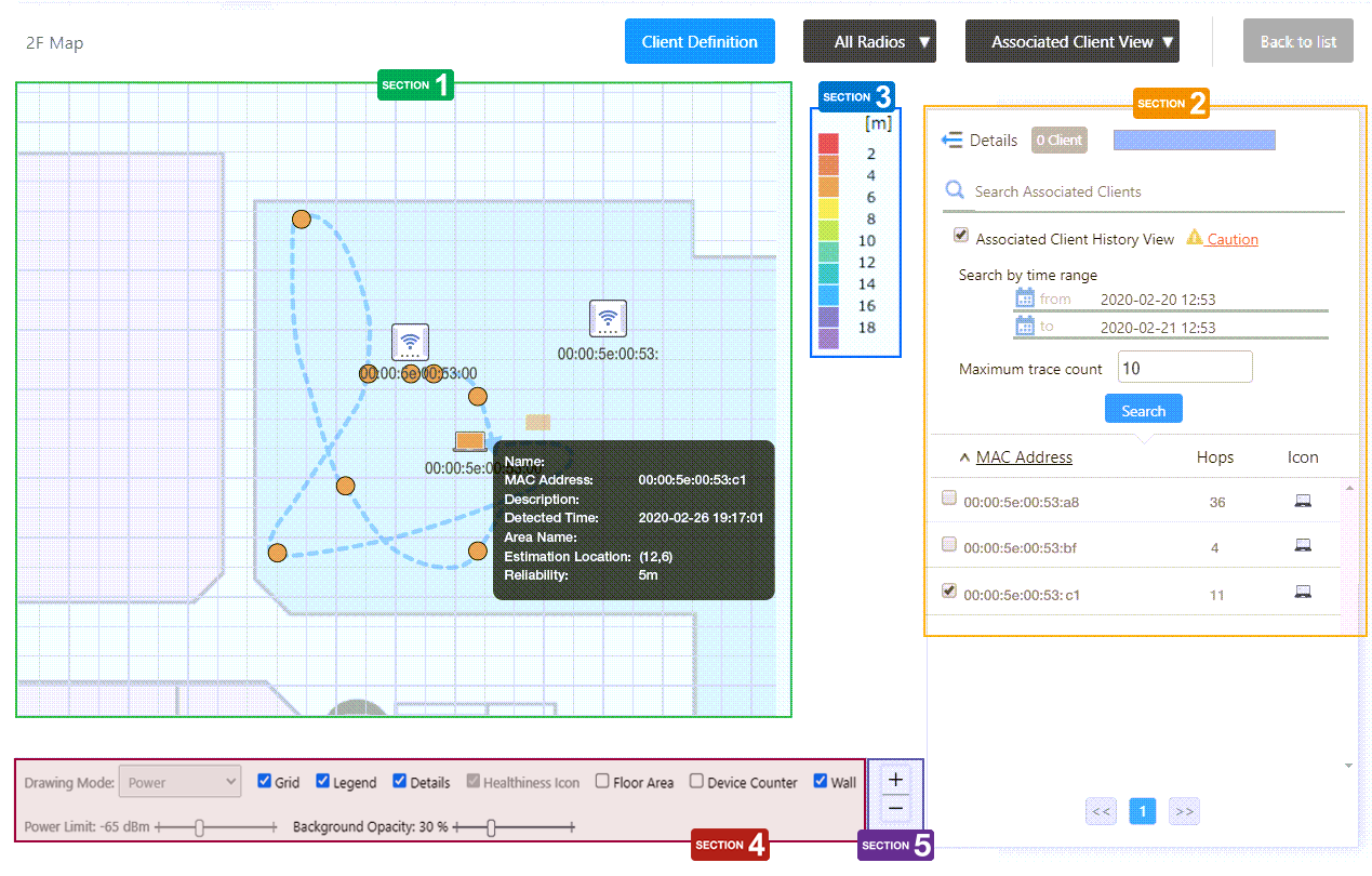
Section 1
Shows the wireless clients that have been connected to the AP on the map.
When you enter a maximum trace count and select a client from the list, the position of that client is drawn on the floor map.
The client's radio wave will be observed by the APs on the floor every minute, and if enough samples to calculate the location are obtained, the AWC plug-in will calculate the estimated location. The calculation may take several minutes after each observation.
Each estimated location is represented by a circle. The color of the circle represents the reliability of the location estimation (see the legend).
The order and direction of the movement are shown as a broken curve and an arrow head. The curve does not necessarily show the exact path the client moved.
You can hover over each circle to see estimation information as a popup balloon.
| Item Name | Description |
|---|---|
| Name | Shows the Client Name if defined in the Client Definition List dialog box. |
| MAC Address | Shows the MAC address of the client. |
| Notes | Shows any comments entered in the "Client Definition List" dialog box. |
| Detected Time | Shows the time the client estimation location was detected. |
| Area Name | Shows the Area Name if the estimated client location is inside an area that has been defined on the "Edit Area" screen. |
| Estimation Location | Shows the coordinates on the grid of the floor map which the client is estimated to be in. The coordinates origin is the top lefthand corner, starting with "(0,0)". |
| Reliability | Shows the reliability, as the possible difference between the estimation and actual location, in metres. |
Section 2
In the Client History List, "Refresh Timer" is disabled.
| Item Name | Description |
|---|---|
| Details | You can click to see Client Name and Notes, in addition to the default items of MAC Address and Hops. Clicking Details again returns you to the default non-detailed view. |
| X Client | Shows the number of clients that had been connected to the AP on the floor map during the specified time period. |
| Search Associated Clients |
Filter entries in the list by entering a partial string in the search box. The Search field lets you enter a partial string to match. The screen displays entries with that string in the "MAC Address" field. To remove the filter, delete the string from the Search field and press Enter. NoteThe search is case-sensitive. |
| Time Search (Start/End) |
Specify a time period with start and end date/time. You can enter a date in "YYYY-MM-DD hh:mm" format or select a day on the calendar that appears when you click the field. |
| Maximum Trace Count |
Specify the maximum number of hops to show. Only the specified number of the most recent hops will be displayed for each client. |
| Search | Search for clients from the list of clients that were connected to the AP on the floor map during the specified time period. |
| Associated Client | |
| Checkbox |
Lets you select wireless clients to be shown on the floor map. When you check a client, an icon, MAC address, and the position of the client are shown on the map. The latest estimated location is represented as the Client Icon (the laptop shape), and each older location estimation is drawn as a circle. The client's estimated trace is also depicted by a broken line. You can click on an icon on the floor map to see the probable circle based on the estimation reliability. You can hover over the icon to see the location estimation information. |
| MAC Address | Shows the MAC address of the wireless client. |
| Hops | Shows the number of estimation entries in the history. |
| Icon |
Displays the wireless client icon shown on the floor map.
|
Section 3
Shows the legend for the Associated Client View.
The color of each cell in the legend represents the reliability of the location estimation of clients shown on the map.
The legend can be made invisible or visible by using a checkbox in the floor map control section at the bottom of the page.
Section 4
In the Associated Client View, "Drawing Mode", "Healthiness Icon", and "Power Limit" are irrelevant and disabled.
| Item Name | Description |
|---|---|
| Grid | Lets you enable or disable grid lines on the floor map. Checking this shows grid lines on the floor map. |
| Legend | Lets you enable or disable the legend. Check to display. |
| Details | Whether to display the Associated Client List. Check to display. |
| Floor Area | If areas have been created on the floor map (using the Edit Area page), lets you choose whether to display the areas. Check to display. |
| Device Counter | On the top left of an area, indicates the number of registered APs that are arranged in the area. |
| Wall | If walls have been created on the floor map (using the Edit Wall page), this lets you choose whether to display the walls. Check to display. |
| Opacity | Specify the opacity of the floor map background image. |
Section 5
Zoom In/Out buttons.
You can zoom in (+) or zoom out (-) of the floor map display. You can also use the mouse wheel scroll to zoom in or out.
Associated Client Roaming History
If the associated client has never met the conditions for showing Client Location Estimation History, and therefore has no location estimation history entries, the Associated Client Roaming History will be displayed instead.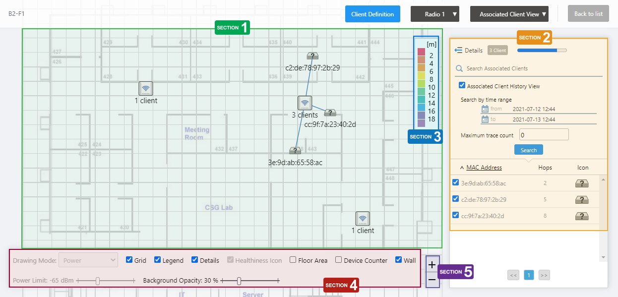
Section 1
Shows the wireless clients that have been connected to the AP on the map.
When you check a client in the list, the floor map shows the history of the APs the selected client had connected to in the past.
Section 2
In the Associated Client Roaming History list, the "Refresh Timer" is disabled.
| Item Name | Description |
|---|---|
| Details | You can click to see Client Name and Notes, in addition to the default items of MAC Address and Hops. Clicking Details again returns you to the default non-detailed view. |
| X Client | Shows the number of clients that had been connected to the AP on the floor map during the specified time period. |
| Search Associated Clients |
Filter entries in the list by entering a partial string in the search box. The Search field lets you enter a partial string to match. The screen displays entries with that string in the "MAC Address" field. To remove the filter, delete the string from the Search field and press Enter. NoteThe search is case-sensitive. |
| Time Search (Start/End) |
Specify a time period with start and end date/time. You can enter a date in "YYYY-MM-DD hh:mm" format or select a day on the calendar that appears when you click the field. |
| Maximum Trace Count |
Specify a maximum hop counts for each client to show on the map. When you specify the limit, only the specified number of the latest hops will be displayed for each client. |
| Search | Search for clients from the list of clients that roamed between the APs on the floor map during the specified time period. |
| Associated Client | |
| Checkbox |
Lets you select wireless clients to be shown on the floor map. When you check a client, an icon and the MAC address of the client are shown near the AP to which the client is associated. If the selected client roamed mutiple times between the APs on the map during the specifed time period, its most recent hop in the roaming history will be shown by the client icon. Earlier positions will be shown by circles. The client's roaming trace will be also depicted by a broken line. You can also see when the client was connected to the AP at the position by clicking a client icon or circles. NoteThe position of the icon does not represent the exact location of the client at the time. Icons are placed so they do not overlap with other icons in the history. |
| MAC Address | Shows the MAC address of the wireless client. |
| Hops | Shows how many times the client roamed between APs in the area. |
| Icon |
Displays the wireless client icon shown on the floor map.
|
Section 3
Shows the legend for the Associated Client View.
Not used in the Associated Client Roaming History View.
Section 4
In the Associated Client View, "Drawing Mode", "Healthiness Icon", and "Power Limit" are irrelevant and disabled.
| Item Name | Description |
|---|---|
| Grid | Lets you enable or disable grid lines on the floor map. Checking this shows grid lines on the floor map. |
| Legend | Lets you enable or disable the legend. Check to display. |
| Details | Whether to display the Associated Client List. Check to display. |
| Floor Area | If areas have been created on the floor map (using the Edit Area page), lets you choose whether to display the areas. Check to display. |
| Device Counter | On the top left of an area, indicates the number of registered APs that are arranged in the area. |
| Wall | If walls have been created on the floor map (using the Edit Wall page), this lets you choose whether to display the walls. Check to display. |
| Opacity | Specify the opacity of the floor map background image. |
Section 5
Zoom In/Out buttons.
You can zoom in (+) or zoom out (-) of the floor map display. You can also use the mouse wheel scroll to zoom in or out.
Associated Client History (Detail)
Clicking "Details" at the top of the client list in "Client Location Estimation History" or "Associated Client Roaming History" extends the list and shows additional information of the histories, if that information has been collected from the APs on the map.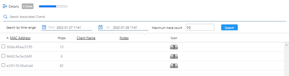
| Item Name | Description |
|---|---|
| Details | You can click to see Client Name and Notes, in addition to the default items of MAC Address and Hops. Clicking Details again returns you to the default non-detailed view. |
| X Client | Shows the number of clients connected to the AP that is selected on the floor map. |
| Search Associated Clients |
Filter entries in the list by entering a partial string in the search box. The Search field lets you enter a partial string to match. The screen displays entries with that string in the "MAC Address" field. To remove the filter, delete the string from the Search field and press Enter. NoteThe search is case-sensitive. |
| "System Info" / "Wireless Info" / "Statistics" buttons | Switches the contents of the list. |
| Time Search (Start/End) |
Specify a time period with start and end date/time. You can enter a date in "YYYY-MM-DD hh:mm" format or select a day on the calendar that appears when you click the field. |
| Maximum Trace Count |
Specify the maximum hop count (location estimation or roaming counts) to show on the map for each client. When you specify the hop limit, only the specified number of the latest hops will be displayed for each client. |
| Search | Search for clients from the list of clients that were connected to the AP on the floor map during the specified time period. |
| Checkbox |
Lets you select wireless clients to be shown on the floor map. When you check a client, an icon and the MAC address of the client are shown near the AP to which the client is associated. If the selected client roamed mutiple times between the APs on the map during the specifed time period, its most recent hop in the roaming history will be shown by the client icon. Earlier positions will be shown by circles. The client's roaming trace will be also depicted by a broken line. You can also see when the client was connected to the AP at the position by clicking a client icon or circles. NoteThe position of the icon does not represent the exact location of the client at the time. Icons are placed so they do not overlap with other icons in the history. |
| MAC Address | Shows the MAC address of the wireless client. |
| Hops | Shows how many times the client had its location estimated or had roamed between APs on the Map. |
| Client Name | Shows the Client Name if defined in the "Client Definition List" dialog box. |
| Notes | Shows any comments entered in the "Client Definition List" dialog box. |
| Icon |
Displays the wireless client icon shown on the floor map.
|
Floor Map [Smart Connect View]
When an AWC-SC Smart Connect network is configured on the floor map, you can display the connection status, the AP roles, and so on.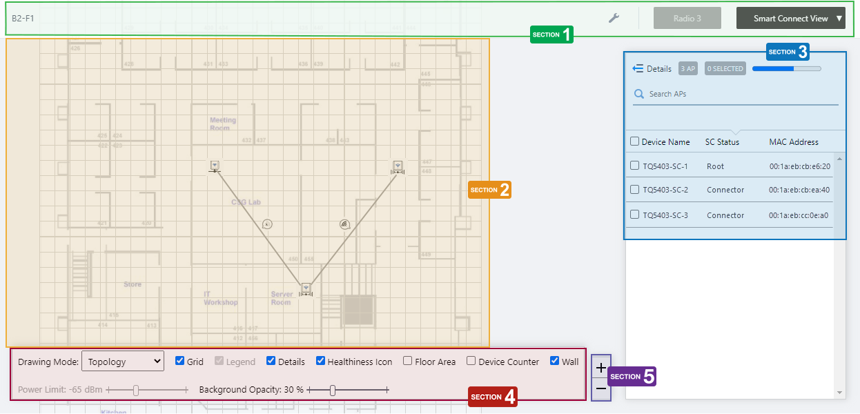
Section 1
| Item Name | Description |
|---|---|
| Management Group / Floor Map Group | The floor map name and the management group of the selected floor map will be displayed. |
| "Spanner" icon |
Hovering the mouse cursor over the Spanner icon shows a dropdown menu including some operations for managed APs. Select APs by checking on the AP list or clicking the AP icons on the floormap, you can then configure the selected APs. You cannot perform Apply Settings, Reboot, Assign Firmware, or Upgrade Firmware in Smart Connect view.
|
| Radio dropdown menu | Disabled in Smart Connect View. |
| View Selection dropdown menu |
Lets you change what information is displayed on the Floor Map Details screen.
|
| "Back to list" button | Click to return to the Floor Map List screen. |
Section 2
- The icon of the wireless AP displays its role in AWC-SC.
- Root AP:
Shown by a wired AP icon.

- Satellite AP (Connector AP or Terminator AP)
Shown by an icon of the AP connected by radio.

- Acting as a Satellite AP in spite of being defined as a Root AP
The UTP cable may be not wired up.

- Acting as a Root AP in spite of being defined as a Satellite AP
A UTP cable may be still connected unintentionally.

- Not acting as an AWC-SC member AP
The AP may not be under management, the firmware may not be up to date, or the required license may not have been applied.

- Root AP:
- You can see the logical connections between the wireless APs by selecting "Topology" from the "Drawing Mode" dropdown menu in the floor map control.
In Topology drawing mode, the link between wireless APs is drawn with a gray line.
When "Healthiness Icon" in the floor map control is checked, the radio wave strength will be indicated by the number of ripples in the balloon of the Healthiness Icon.
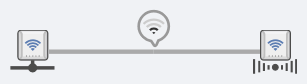
Table 39: Healthiness Icons
Number of bars Power 
4 -57dBm or greater 
3 -62 to -58dBm 
2 -69 to -63dBm 
1 -79 to -70dBm 
0 -80dBm or less
- You can see the traffic utilization between the wireless APs by selecting "Traffic" from the "Drawing Mode" dropdown menu in the floor map control.
In the Traffic drawing mode, the link line is divided in the middle, and each half depicts the utilization rate from the AP linked directly. For example, in the link between AP1 and AP2, the half nearer to AP1 shows the transmission utilization rate from AP1 to AP2, and the half nearer to AP2 shows transmission from AP2 to AP1.
The color of the half link indicates the utilization rate.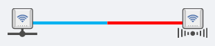
The utilization rate is calculated based on the link speed and the amount of traffic between the APs.
- Light blue: 0 to 25%
- Green: 25 to 50%
- Yellow: 50 to 75%
- Red: 75 to 100%
- Light blue: 0 to 25%
Section 3
| Item Name | Description |
|---|---|
| Details | Clicking this shows Acceptor and Connector Tx / Rx Bytes per second and tags, in addition to the default items (Device Name, SC Status, and MAC Address). Clicking Details again returns you to the default non-detailed view. |
| X AP | Shows the number of wireless APs placed on the floor map. This includes APs on which Smart Connect is not enabled or available. |
| Refresh Timer | Shows the status of the timer that automatically refreshes the page with the blue progress bar. The list is automatically refreshed at the interval configured on "Refresh Rates" > "Floor MAP (Smart Connect)" in the User Management menu. (The default is 5 seconds.) |
| Search Wireless AP |
The Search field lets you enter a partial string to match. The screen displays entries with that string in one of the following fields: "Device Name", "SC Status", or "MAC Address" fields. To remove the filter, delete the string from the Search field and press Enter. NoteThe search is case-sensitive. |
| Device Name | Shows the name given to the AP. |
| SC Status |
Shows the AP's role in AWC-SC.
|
| MAC Address | Shows the device's MAC address. |
Section 4
In the Smart Connect View, "Power Limit" is does not apply and is disabled.
Also, when the drawing mode is "Topology", "Legend" will be disabled, and when the drawing mode is "Traffic", the "Healthiness Icon" will be disabled.

| Item Name | Description |
|---|---|
| Drawing Mode | You can select the mode that the link lines between APs on the floor map represent, either "Topology" or "Traffic". |
| Grid | Lets you enable or disable grid lines on the floor map. Checking this shows grid lines on the floor map. |
| Legend | Lets you enable or disable the legend. Check to display. |
| Details | Toggles the visibility of the AP List. Check to display. |
| Healthiness Icon | In Topology drawing mode, lets you choose whether to display the Healthiness Icon. Check to display. |
| Floor Area | If areas have been created on the floor map (using the Edit Area page), lets you choose whether to display the areas. Check to display. |
| Device Counter | On the top left of an area, indicates the number of registered APs that are arranged in the area. |
| Wall | If walls have been created on the floor map (using the Edit Wall page), this lets you choose whether to display the walls. Check to display. |
| Opacity | Specify the opacity of the floor map background image. |
Section 5
Zoom In/Out buttons.
You can zoom in (+) or zoom out (-) of the floor map display. You can also use the mouse wheel scroll to zoom in or out.
Smart Connect AP List (Detail)
Clicking "Details" at the top of the AP list in the "Smart Connect View" extends the list to show additional information such as SC Status and Tx / Rx throughput.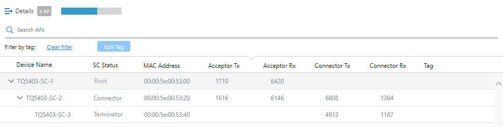
| Item Name | Description |
|---|---|
| Details | Clicking this shows Acceptor and Connector Tx / Rx Bytes per second and tags, in addition to the default items (Device Name, SC Status, and MAC Address). Clicking Details again returns you to the default non-detailed view. |
| X AP | Shows the number of wireless APs placed on the floor map. This includes APs on which Smart Connect is not enabled or available. |
| Refresh Timer | Shows the status of the timer that automatically refreshes the page with the blue progress bar. The list is automatically refreshed at the interval configured on "Refresh Rates" > "Floor MAP (Smart Connect)" in the User Management menu. (The default is 5 seconds.) |
| Search Wireless AP |
You can search for wireless APs on the floor map. The Search field lets you enter a partial string to match. The screen displays entries with that string in one of the following fields: "Device Name", "SC Status", or "MAC Address" fields. To remove the filter, delete the string from the Search field and press Enter. NoteThe search is case-sensitive. |
| Device Name | Shows the name given to the AP. |
| SC Status |
Shows the AP's role in AWC-SC.
|
| MAC Address | Shows the device's MAC address. |
| Acceptor Tx | Shows the throughput of the traffic transmitted to the downlink AP (Terminator AP for Root/Connector APs, and Connector AP for Root AP) in bytes per second. |
| Acceptor Rx | Shows the throughput of the traffic received from the downlink AP (the Terminator AP for Root/Connector APs, and the Connector AP for the Root AP) in bytes per second. |
| Connector Tx | Shows the throughput of the traffic transmitted to the uplink AP (the Root AP for Connector/Terminator APs, and the Connector AP for the Terminator AP) in bytes per second. |
| Connector Rx | Shows the throughput of the traffic received from the uplink AP (the Root AP for Connector/Terminator APs, and the Connector AP for the Terminator AP) in bytes per second. |
| Tag | Shows the tags set on the AP. |
Floor Map [Rogue AP View]
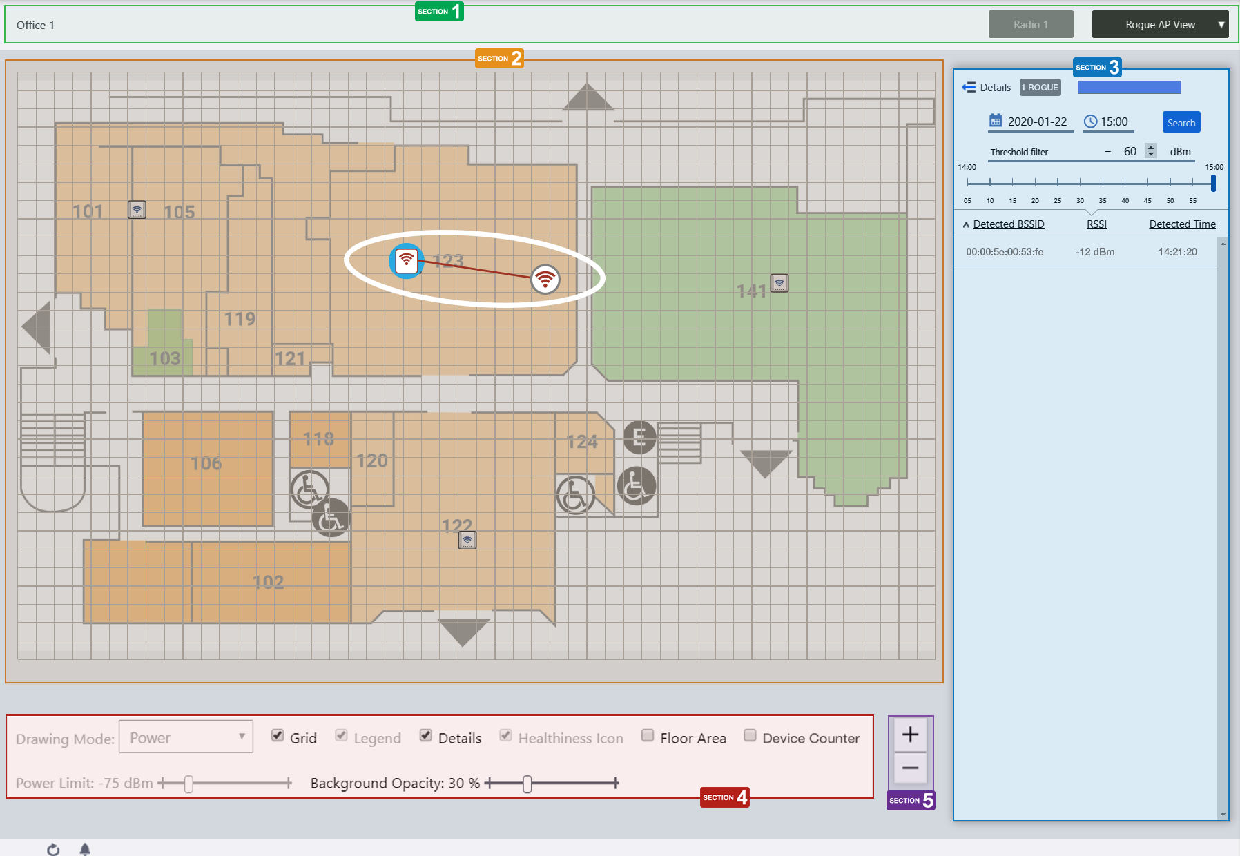
Section 1
| Item Name | Description |
|---|---|
| Management Group / Floor Map Group | The floor map name and the management group of the selected floor map will be displayed. |
| Radio dropdown menu | Disabled in Rogue AP View. |
| View Selection dropdown menu |
Lets you change what information is displayed on the Floor Map Details screen.
|
| "Back to list" button | Click to return to the Floor Map List screen. |
Section 2
- Managed AP icons turn red on the map if there are rogue AP detection reports by the managed AP during the time period specified in section 3.
- Clicking a managed AP on the map toggles display status of the detected rogue APs.
Note
The position of the rogue AP icon does not represent the exact location of the rogue AP at the time. Icons are placed to not overlap with other icons in the history.
- When you click a rogue AP icon on the floor map, the corresponding entry in section 3 is highlighted.
Section 3
In Rogue AP View, "Refresh Timer" is disabled.
| Item Name | Description |
|---|---|
| Details | Clicking this shows the reason to consider the detected neighbor AP a rogue, the SSID, Channel and detecting AP, in addition to the default items (BSSID, RSSI and Detection Time). Clicking Details again returns you to the default non-detailed view. |
| X ROGUE | Shows the number of rogue APs that match the specified time period and received signal strength. |
| Date/Time |
Specify a date and time, to filter rogue APs on the list. You can enter a date in "YYYY-MM-DD hh:mm" format or select a day on the calendar that appears when you click the field. The time can be selected in one-hour intervals. Alternatively, a slider control lets you specify a more granular time. |
| Search | Filters rogue AP detection history by the specifed date/time. |
| Threshold Filter |
Specify a minimum received signal strength for a rogue AP to be displayed. Rogue APs are only shown on the list and floor map if the received signal strength of the rogue AP is greater than the specified minimum value. |
| Slider Control | Lets you specify detection time in 5 minute intervals. |
| Rogue AP List | |
| Detected BSSID |
Shows a list of BSSIDs that managed APs on the map detected. Clicking a rogue AP entry in the list toggles display of all rogue AP icons detected by the managed APs. When the display status of a rogue AP icon is enabled, you can highlight the rogue AP's icon on the floor map by hovering over the rogue AP entry in the list. |
| RSSI | Received Signal Strength of the rogue AP observed on the detecting managed AP. A higher value (closer to 0) means a stronger signal, therefore the rogue AP may be closer to the detecting managed AP. |
| Detected Time | Shows the date/time when the managed AP detected the rogue AP. |
Section 4
In the Rogue AP View, "Drawing Mode", "Legend", "Healthiness Icon", and "Power Limit" are irrelevant and disabled.

| Item Name | Description |
|---|---|
| Grid | Lets you enable or disable grid lines on the floor map. Checking this shows grid lines on the floor map. |
| Details | Toggles the visibility of the Rogue AP List. Check to display. |
| Floor Area | If areas have been created on the floor map (using the Edit Area page), lets you choose whether to display the areas. Check to display. |
| Device Counter | On the top left of an area, indicates the number of registered APs that are arranged in the area. |
| Wall | If walls have been created on the floor map (using the Edit Wall page), this lets you choose whether to display the walls. Check to display. |
| Opacity | Specify the opacity of the floor map background image. |
Section 5
Zoom In/Out buttons.
You can zoom in (+) or zoom out (-) of the floor map display. You can also use the mouse wheel scroll to zoom in or out.
Rogue AP List (Detail)
Clicking "Details" at the top of the Rogue AP list on "Floor Map [Rogue AP View]" extends the list to show additional information such as Rogue Reason, SSID, Channel and Detecting AP.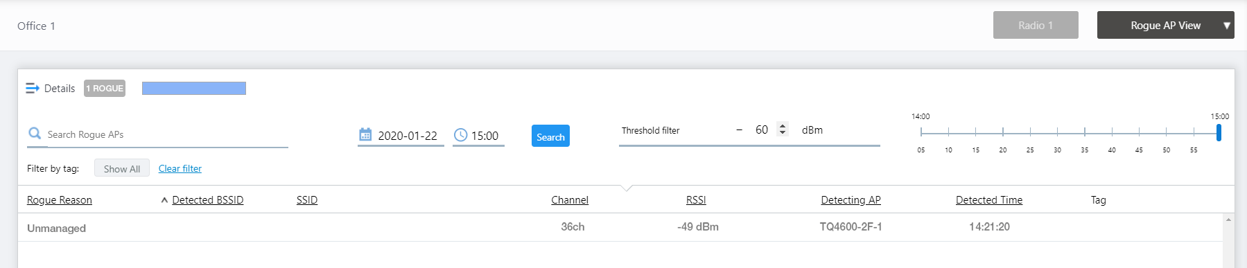
| Item Name | Description |
|---|---|
| Details | Clicking this shows the reason to consider the detected neighbor AP a rogue, the SSID, Channel and detecting AP, in addition to the default items (BSSID, RSSI and Detection Time). Clicking Details again returns you to the default non-detailed view. |
| X ROGUE | Shows the number of rogue APs that match the specified time period and received signal strength. |
| Search Rogue AP |
Filter entries in the list by entering a partial string in the search box. The Search field lets you enter a partial string to match. The screen displays entries with that string in one of the following fields: "BSSID" or "SSID". To remove the filter, delete the string from the Search field and press Enter. NoteThe search is case-sensitive. |
| Date/Time |
Specify a date and time, to filter rogue APs on the list. You can enter a date in "YYYY-MM-DD hh:mm" format or select a day on the calendar that appears when you click the field. The time can be selected in one-hour intervals. Alternatively, a slider control lets you specify a more granular time. |
| Search | Filters rogue AP detection history by the specifed date/time. |
| Threshold Filter |
Specify a minimum received signal strength for a rogue AP to be displayed. Rogue APs are only shown on the list and floor map if the received signal strength of the rogue AP is greater than the specified minimum value. |
| Slider Control | Lets you specify detection time in 5 minute intervals. |
| Filter by tag | Lets you filter APs with tags. Clicking tags uses tags to filter the list. Clicking them again removes the filter. Clicking "Clear filter" removes the filter for all tags. |
| Rogue AP List | |
| Rogue Reason | Shows the reason to consider the detected neighbor AP a rogue. |
| Detected BSSID | Shows a list of BSSIDs that managed APs on the map detected. |
| SSID | Shows the SSID of the detected AP. |
| RSSI | Received Signal Strength of the rogue AP observed on the detecting managed AP. A higher value (closer to 0) means a stronger signal, therefore the rogue AP may be closer to the detecting managed AP. |
| Detecting AP | Shows the AP name which detected the neighbor AP. |
| Detected Time | Shows the date/time when the managed AP detected the rogue AP. |
| Tag | Shows tags added to the AP. |
Floor Map [Add AP to Map]
In this view, you can place an AP on the floor map.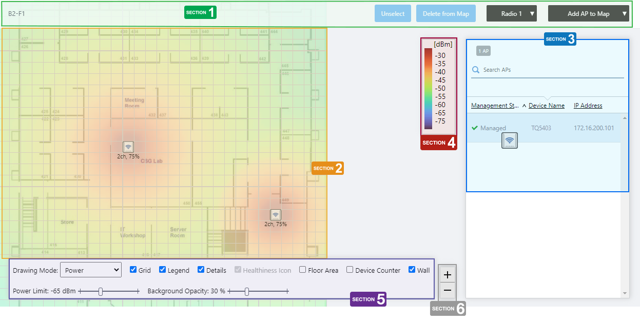
Section 1
| Item Name | Description |
|---|---|
| Management Group / Floor Map Group | The floor map name and the management group of the selected floor map will be displayed. |
| "Unselect" button | Deselects the currently selected (highlighted by blue dot) wireless APs. |
| "Delete from Map" button | Removes the currently selected (highlighted by blue dot) wireless APs from the map. |
| Radio dropdown menu | Select which radio band information to display from Radio 1, Radio 2, Radio 3, or "All Radios". The default is "All Radios". If you select "All Radios", Associated Client Information for all bands (Radio 1, Radio 2, and Radio 3) will be displayed. |
| View Selection dropdown menu |
Lets you change what information is displayed on the Floor Map Details screen.
|
| "Back to list" button | Click to return to the Floor Map List screen. |
Section 2
- When you click the row of the AP you want to place on the Map from the list of unallocated APs in Section 3, the mouse pointer changes to the wireless AP icon.
By clicking on the grid of the floor map with the icon, you can place the AP on the floor map.
- The status of the placed AP will be displayed on the floor map, depending on what you previously selected in the View Selection dropdown menu. If you selected "Smart Connect View" in the dropdown menu, you will see the AP's Smart Connect status, and if you selected a different view, the AP status will be drawn on the floor map according to the "Wireless Status View".
- If you want to move an AP icon on the floor map, you can drag and drop it on the place you want it to move to.
- To remove an AP icon on the floor map, click on it to select it (the selected icon will drawn with a blue circle behind it) and then click the "Delete from Map" button at the top right of the content section.
You can select multiple APs by clicking them one by one.
To deselect, click on the "Unselect" button at the top right of the content section.
Section 3
Shows the wireless AP list.
The list contains only the APs that belong to the same management group as the map, and that are not yet placed on any map.
| Item Name | Description |
|---|---|
| X AP | Displays the number of wireless APs under the management group to which the floor map belongs, that are not yet placed on any floor map. |
| Search Wireless AP |
You can search for wireless APs not placed on the floor map. The Search field lets you enter a partial string to match. The screen displays entries with that string in one of the following fields: "Management Status", "Device Name", "IP address", or "AP Profile". To remove the filter, delete the string from the Search field and press Enter. NoteThe search is case-sensitive. |
| Device Name | Shows the name given to the AP. |
| Status Icon | When the AP is managed by the AWC Plug-in, a green checkmark is displayed. When the AP is not managed by the AWC Plug-in, a red triangle is displayed. |
| Management Status | Shows the management status of the AP. |
| IP Address | Shows the AP's IP address. |
Section 4
Shows the legend of either the Wireless Status View or Smart Connect View.
The legend will be shown according to the immediately previous selection of the Views; the Smart Connect View legend for Smart Connect View, and the Wireless Status View legend for the others.
Section 5
The legend will be shown according to the immediately previous selection of the Views; the Smart Connect View legend for Smart Connect View, and the Wireless Status View legend for the others.
| Item Name | Description |
|---|---|
| Drawing Mode | The options in the Drawing Mode dropdown menu differ according to the immediately previous selection of the Views. If you chose Smart Connect View previously, the Drawing Mode dropdown comes with Topology and Traffic, and if you chose another view, the dropdown comes with Power and Channel. |
| Grid | Lets you enable or disable grid lines on the floor map. Checking this shows grid lines on the floor map. |
| Legend | Lets you enable or disable the legend. Check to display. |
| Details | Whether to display List of unallocated APs. Check to display. |
| Healthiness Icon | Whether to display the Healthiness Icon. This will work if you chose Smart Connect View from the View Selection dropdown menu immediately before, and you chose Topology from the Drawing Mode. Otherwise, this is irrelevant and disabled. Check to display. |
| Floor Area | If areas have been created on the floor map (using the Edit Area page), lets you choose whether to display the areas. Check to display. |
| Device Counter | On the top left of an area, indicates the number of registered APs that are arranged in the area. |
| Power Limit | You can set the lower limit of the wireless strength that is drawn on the heat map display, if you chose a view other than Smart Connect View from the View Selection dropdown menu immediately before. |
| Wall | If walls have been created on the floor map (using the Edit Wall page), this lets you choose whether to display the walls. Check to display. |
| Opacity | Specify the opacity of the floor map background image. |
Section 6
Zoom In/Out buttons.
You can zoom in (+) or zoom out (-) of the floor map display. You can also use the mouse wheel scroll to zoom in or out.
Floor Map [Edit Area]
You can draw areas (rooms, etc.) with planar polygons, and name these areas such as "Meeting Room", "Lounge", and "Auditorium" on the floor map.The defined areas will be displayed in each View of the floor map, and also shown in the Location Estimation popup information in the Associated Client View.
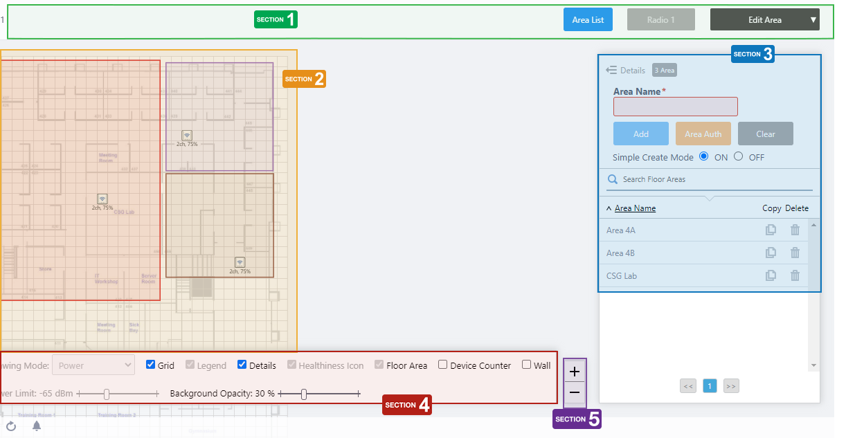
Section 1
| Item Name | Description |
|---|---|
| Management Group / Floor Map Group | The floor map name and the management group of the selected floor map will be displayed. |
| "Area List" button |
Opens "Area List In This Floor" dialog box. 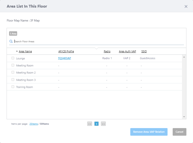 Lists all the areas created on this floor map, along with information of Area Authentication VAPs associated with each area.
|
| Radio dropdown menu | Lets you select a radio band to show on the map, from Radio 1, 2 or 3. |
| View Selection dropdown menu |
Lets you change what information is displayed on the Floor Map Details screen.
|
| "Back to list" button | Click to return to the Floor Map List screen. |
Section 2
You can view and draw areas.
- Start by drawing an area on the map, as a polygon or rectangle. The colors of the areas are not configurable manually but are chosen randomly.
Enter an "Area Name" and click on the "Add" button to save the area you drew on the map.
- When you hover over an existing area, a popup balloon shows the area information.
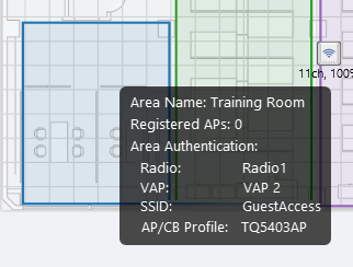
- Area Name:
Shows the area name configured.
- Registered AP count:
Shows the number of the APs placed inside the area.
- Area Authentication:
When the area authentications is configured on this area, displays the radio band, VAP name, SSID, and AP/CB Profile applied to the area.
When the area authentication is not set, shows as it is, "Not Set".
- Area Name:
- By clicking on an area, you can edit it.
- You can reshape it by using the drag-and-drop on each corner point.
Note
You can not add or delete corner points.
- Edit "Area Name" to change the area name.
- You can reshape it by using the drag-and-drop on each corner point.
NoteAreas must be drawn so that they do not overlap. For example, to create an area that surrounds another area, such as a corridor, divide the area into two or more areas.
If areas overlap, the Client Location Estimation display might become inaccurate.
Section 3
Shows the Area list.
| Item Name | Description |
|---|---|
| X Area | Shows the number of areas defined on the floor map. |
| Area Name | The area name displayed in the "Associated Client View". |
| "Add" / "Save" button | Saves a newly created area or edited existing area. You can create a new area by drawing a polygon or a rectangle on the floor map, entering Area Name, and clicking on the "Add" button. |
| "Area Auth" button: |
Opens "Edit Area-VAP Relation" dialog box to select the Area Authentication VAP you want to set available only in the area. The "Area Auth" button will not be enabled while you are just creating a new area, that is, the button will be enabled once you add and select an area. 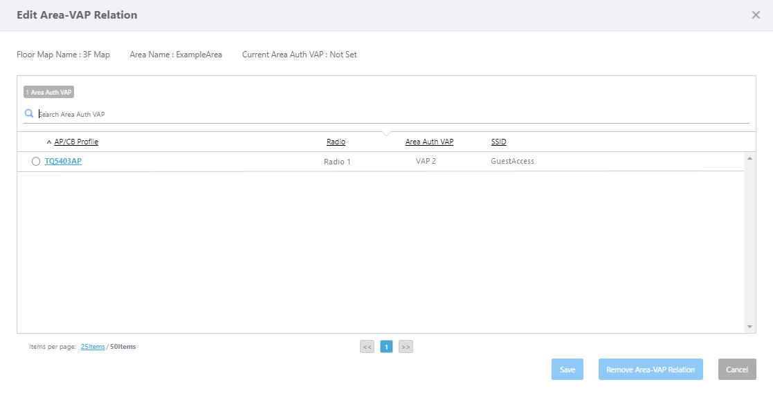 The Area Authentication VAP means the VAP whose "Area Authentication" option is enabled in AP Profile or CB Profile. By associating the area with the Area Authentication VAP, only wireless clients whose locations are estimated as in the area can be allowed to connect to the VAP. Only one Area Authentication VAP can be associated to a single area.
|
| "Clear" / "Cancel" button | Cancels changes before clicking the "Add" / "Save" button. |
| "Simple Create Mode" vs "Normal Create Mode" radio button |
Switches the drawing mode of the area. Do not confuse with the Drawing Mode of Views such as Channel and Power, or Topology or Traffic. The default is "Simple Create Mode".
|
| Search Floor Areas |
You can search for particular areas on the floor map. The Search field lets you enter a partial string to match. The screen displays entries with that string in the "Area Name" field. To remove the filter, delete the string from the Search field and press Enter. NoteThe search is case-sensitive. |
| Area Name | Shows the area name defined for display. In addition, a lock icon is displayed in the area name of the area associated with the Area Authentication VAP. |
| "Edit" button | Enters edit mode for the selected area. |
| "Copy" button | Duplicates the selected area. The Area Name of the duplicated area will be the original Area Name plus "_copy". If this name is already in use, a sequential number with brackets follows the suffix, such as "_copy(1)". The duplicated area polygon will be the same shape and will be placed at the top left of the map. Move and reshape it as needed. |
| "Delete" button | Deletes the selected area. |
Section 4

| Item Name | Description |
|---|---|
| Grid | Lets you enable or disable grid lines on the floor map. Checking this shows grid lines on the floor map. |
| Details | Toggles the visibility of Area List. Check to display. |
| Floor Area | If areas have been created on the floor map (using the Edit Area page), lets you choose whether to display the areas. Check to display. |
| Device Counter | On the top left of an area, indicates the number of registered APs that are arranged in the area. |
| Wall | If walls have been created on the floor map (using the Edit Wall page), this lets you choose whether to display the walls. Check to display. |
| Opacity | Specify the opacity of the floor map background image. |
Section 5
Zoom In/Out buttons.
You can zoom in (+) or zoom out (-) of the floor map display. You can also use the mouse wheel scroll to zoom in or out.
Floor Map [Edit Wall]
You can draw walls with polylines to simulate radio attenuation by walls, partitions, and pillars on the floor map.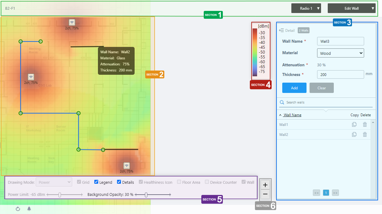
Section 1
| Item Name | Description |
|---|---|
| Management Group / Floor Map Group | The floor map name and the management group of the selected floor map will be displayed. |
| Radio dropdown menu | Lets you select a radio band to show on the map, from Radio 1, 2 or 3. |
| View Selection dropdown menu |
Lets you change what information is displayed on the Floor Map Details screen.
|
| "Back to list" button | Click to return to the Floor Map List screen. |
Section 2
You can view and draw walls.
- Type in the "Wall Name" field to turn on wall edit mode. A crosshair mouse pointer will appear.
- Click on the corner of a wall with the crosshair mouse pointer to start drawing the wall as a polyline.
- To finish drawing a wall, double-click on the end point of the wall.
- You can reshape it by using the drag-and-drop on each corner point.
Note
You can not add or delete corner points.
- Click on the corner of a wall with the crosshair mouse pointer to start drawing the wall as a polyline.
- When you hover over an existing wall, a popup balloon shows the wall information.
- Wall Name:
Shows the wall name configured.
- Material:
Shows the material name specified.
- Attenuation:
Shows the attenuation rate according to the wall material, or specified manually (unit: %).
- Thickness:
Shows the wall thickness (unit: mm).
- Wall Name:
Section 3
Shows the list of Walls.
| Item Name | Description |
|---|---|
| X Walls | Shows the number of walls defined on the floor map. |
| Wall Name | Shows the wall name. |
| Material |
Select a wall material from the drop-down list. The attenuation factor varies according to the wall material. The preset materials and attenuation factor are as follows:
|
| Attenuation | Shows the attenuation factor according to the selected material. If "User Specified" is selected for the material, enter a value between 1 and 99 (unit: %), depending on the attenuation by the actual wall. |
| Thickness | Specify the thickness of the wall with a value from 1 to 32767 (unit: mm). |
| "Add" / "Save" button | Saves a newly created wall or edited an existing wall. You can add a wall by typing the wall name, then drawing a polyline on the floor map. |
| "Clear" / "Cancel" button | Cancels changes before clicking the "Add" / "Save" button. |
| Search walls |
You can search for particular walls on the floor map. The search field lets you enter a partial string to match. The screen displays entries with that string in the "Wall Name" field. To remove the filter, delete the string from the Search field and press Enter. NoteThe search is case-sensitive. |
| Wall Name | Shows the wall name defined for display. |
| "Copy" button | Duplicates the selected wall. The wall name of the duplicated wall will be the original wall name plus "_copy". If this name is already in use, a sequential number with brackets follows the suffix, such as "_copy(1)". The duplicated wall polyline will be the same shape and will be placed at the lower right adjacent to the original. Move and reshape it as needed. |
| "Delete" button | Deletes the selected wall. |
Section 4
Shows the legend of the Wireless Status View.
Section 5
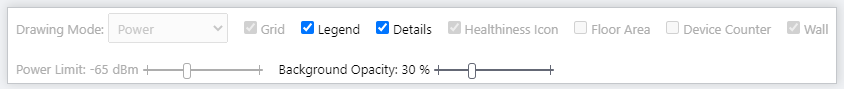
| Item Name | Description |
|---|---|
| Grid | Lets you enable or disable grid lines on the floor map. |
| Legend | Lets you enable or disable the legend. Check to display. |
| Details | Toggles the visibility of Area List. Check to display. |
| Wall | If walls have been created on the floor map (using the Edit Wall page), this lets you choose whether to display the walls. |
| Opacity | Specify the opacity of the floor map background image. |
Section 6
Zoom In/Out buttons.
You can zoom in (+) or zoom out (-) of the floor map display. You can also use the mouse wheel scroll to zoom in or out.
21 Oct 2022 11:56