3D Floor Map [Smart Connect View]
On the 3D Floor Map view, select "Smart Connect View" from the View Selection dropdown menu to display the information of the Smart Connect on the currently selected floor maps.
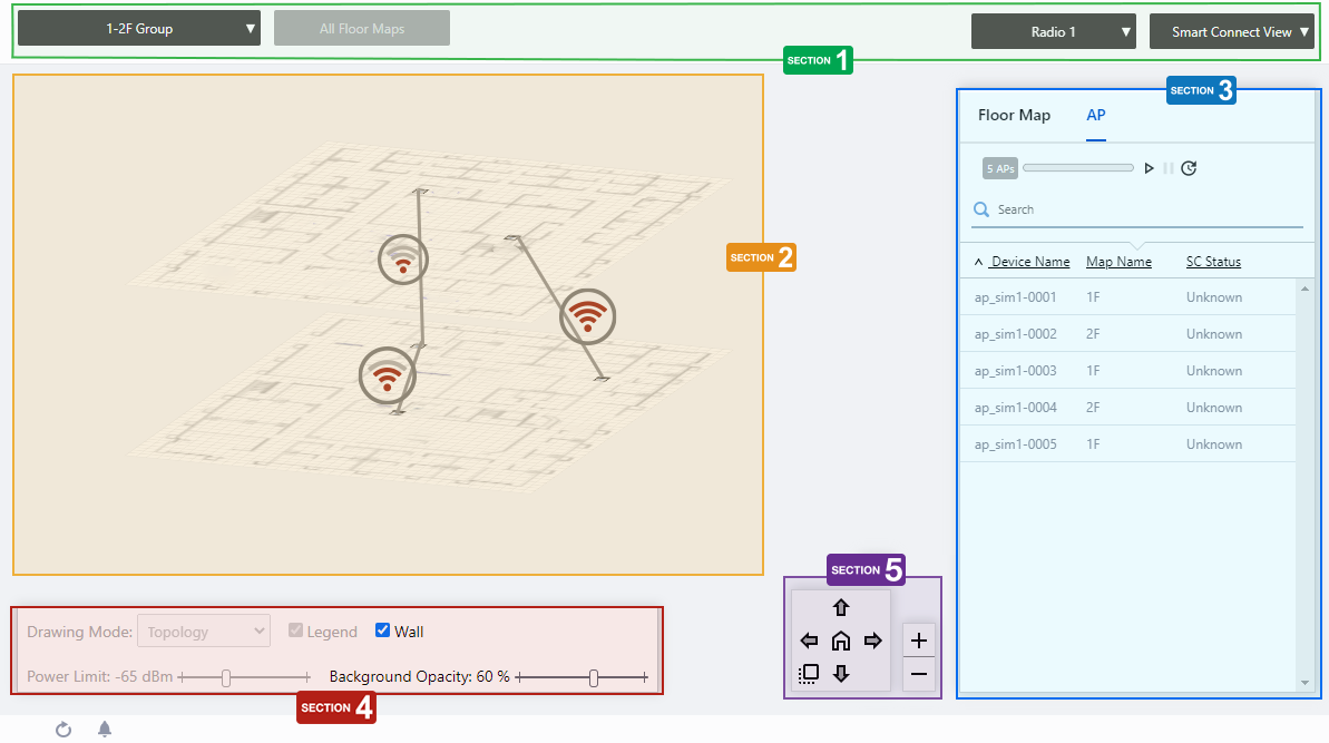
Section 1
| Item Name | Description |
|---|---|
| Management group drop-down menu | Narrow down the floor map to be displayed. If you change the currently selected management group, the 3D Floor Map view will be canceled and you will return to the Floor Map List panel view. |
| Floor Map drop-down menu | Disabled on 3D floor map. |
| Radio dropdown menu | Lets you select a radio band to show on the map, from Radio 1, 2 or 3. |
| View Selection dropdown menu | Lets you change what information is displayed on the Floor Map Details screen.
|
Section 2
The selected floor map will be displayed layer by layer.
The display angle of the floor maps can be controlled using the angle adjustment buttons on the bottom right.
Each floor map shows the icons of the APs placed and the walls created in the individual floor map detail view. When the APs are wirelessly connected by AWC-SC, the connection status between the APs is indicated by a gray link line and a healthiness icon.
The healthiness icon indicates the strength of the signal between APs by the number of ripples in the icon.
| Number of bars | Power | |
|---|---|---|
| 4 | -57dBm or greater | |
| 3 | -62 to -58dBm | |
| 2 | -69 to -63dBm | |
| 1 | -79 to -70dBm | |
| 0 | -80dBm or less | |
- Wireless AP Name
- MAC Address
- IP Address
Section 3
Floor maps / wireless AP list will be displayed. You can switch between the floor map list and the wireless AP list using the tabs at the top of the list.
Place the mouse pointer on any line in the floor map list to highlight the corresponding floor map in the layered view.
Also, when you place the mouse pointer on any line of the wireless AP list, the corresponding wireless AP icon on the floor map will be highlighted with a blue dot.
| Item Name | Description |
|---|---|
| Header | |
| Floor Map/AP Tab | Switches the contents of the list. |
| Floor Map List | |
| X Deployment Map | Displays the number of floor maps that belong to the selected management group. |
| Refresh Timer | Shows the status of the timer that automatically refreshes the page with the blue progress bar. In the 3D floor maps view, the resume/pause automatic update buttons and the manual update button are displayed along with a progress bar. By default, automatic updates are paused. |
| Search Floor Map | Disabled on 3D floor map. |
| Checkbox | Check this box if you want to select the floor map as the display target. |
| Floor Map | The floor map names belonging to the selected management group will be displayed. |
| Origin | Displays the upper left coordinate of the floor map image. |
| Height | Displays the set ceiling height of the floor. |
| Order | You can change the order of the floor map by clicking and holding the mouse pointer up or down. |
| Edit (pencil icon) | The "Edit 3D Map Settings" dialog box will appear. ◼ Edit 3D Map Settings 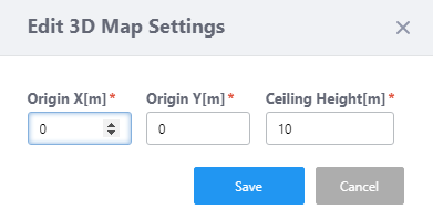
|
| AP list | |
| X AP | Shows the number of APs placed on the floor map. |
| Refresh Timer | Shows the status of the timer that automatically refreshes the page with the blue progress bar. In the 3D floor maps view, the resume/pause automatic update buttons and the manual update button are displayed along with a progress bar. By default, automatic updates are paused. |
| "Search" box | Filter entries in the list by entering a partial string in the search box. Displays the items among the current display targets that contain the string entered in this field in either " Device Name" or "Floor Map Name". To remove the filter, delete the string from the Search field and press Enter. NoteThe search is case-sensitive. |
| Device Name | Shows the name given to the AP. |
| Floor Map Name | The name of the floor map the AP belongs to is displayed. |
| SC Status | Shows the AP's role in AWC-SC.
|
Section 4
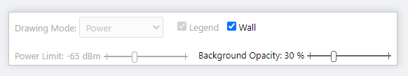
The Drawing Mode, Legend, and Power Limit are disabled in the Smart Connect View of the 3D floor maps.
| Item Name | Description |
|---|---|
| Wall | If walls have been created on the floor map (using the Edit Wall page), this lets you choose whether to display the walls. Check to display.NoteIf walls have been defined, attenuation by the walls takes effect on the heat map even when this control is left unchecked. |
| Opacity | Specify the opacity of the floor map background image. |
Section 5
Adjusts the display size and angle of the map.
- Zoom In/Out buttons
You can zoom in (+) or zoom out (-) of the floor map display. You can also use the mouse wheel scroll to zoom in or out.

- Angle adjustment buttons
Only in the layered view, the angle at which the floor map is displayed can be adjusted using the arrow buttons.
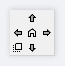
- Up/Down arrows: Adjust the vertical (pitch) angle.
- Left/Right arrows: Adjust the horizontal rotation (yaw) angle.
- Plan view button (left-bottom): All floors are superimposed and displayed as a plan view looking down from above.
- Home position (center): Returns the angle of view to the initial state.
- Up/Down arrows: Adjust the vertical (pitch) angle.
11 Jul 2024 13:42