Configure the AWC Plug-in
Register the TQ6702 GEN2-R (wireless AP router) configured as a wireless LAN router to the AWC Plug-in.
Please note that in order to create AP common settings and assign reading permission to specific user accounts, it is necessary to create a management group and an account in advance. To create a management group and a account according to your environment, please refer to Quick Tour > Configure Multi-channel Wireless Network > Create Management Group to Quick Tour > Configure Multi-channel Wireless Network > Create Account.
Create AP Profile
First, let's create an AP profile for TQ6702 GEN2-R.- Select "Wireless Configuration" > "AP Profile" from the AWC Plug-in menu.
The AP Profile list screen will appear.
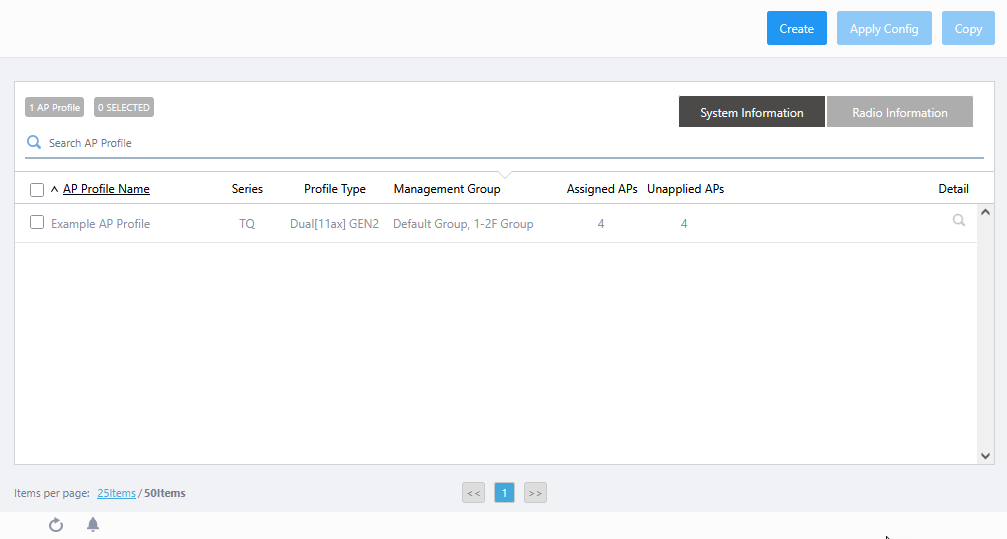
- Click "Create" at the top right of the screen.
The "Select Country, AP Series and Model" dialog box will appear.
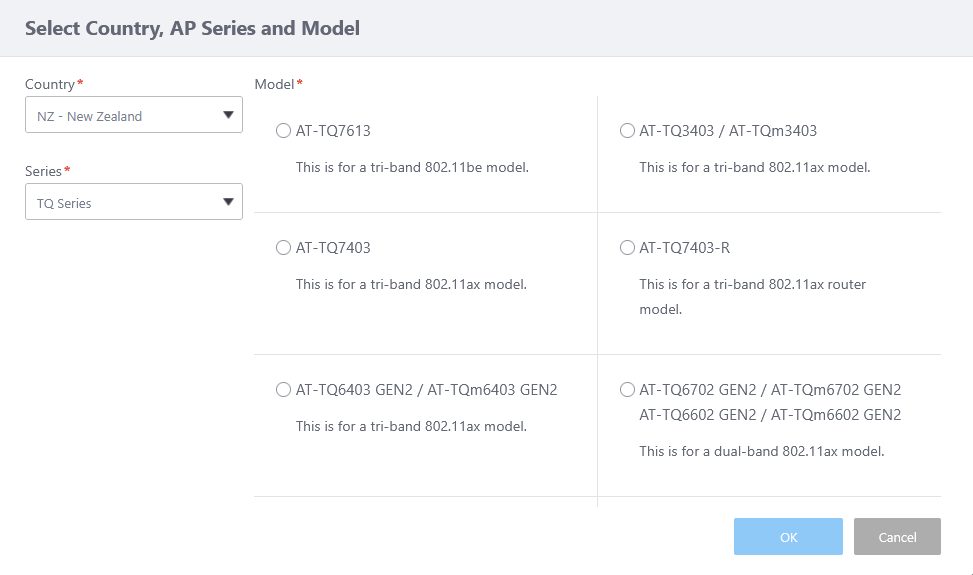
- Select a Country.
If the default country code for the currently logged in user is configured, it is selected by default.
- Select "TQ Series" from "Series".
- Select a Model.
There are several options for this item, depending on the supported feature set of the AP model.
Select "AT-TQ6702 GEN2-R", the model to be used in this case.
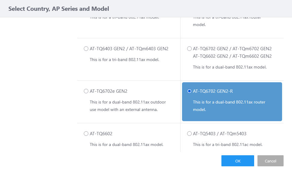
- Click "OK".
The AP profile configuration screen will appear.
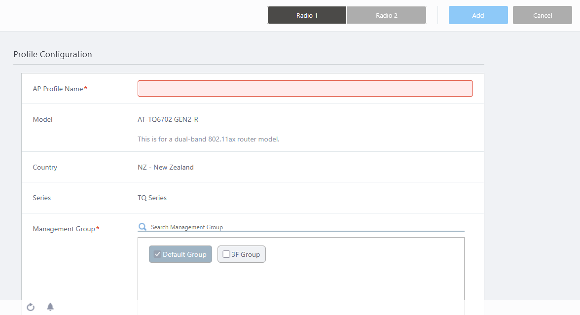
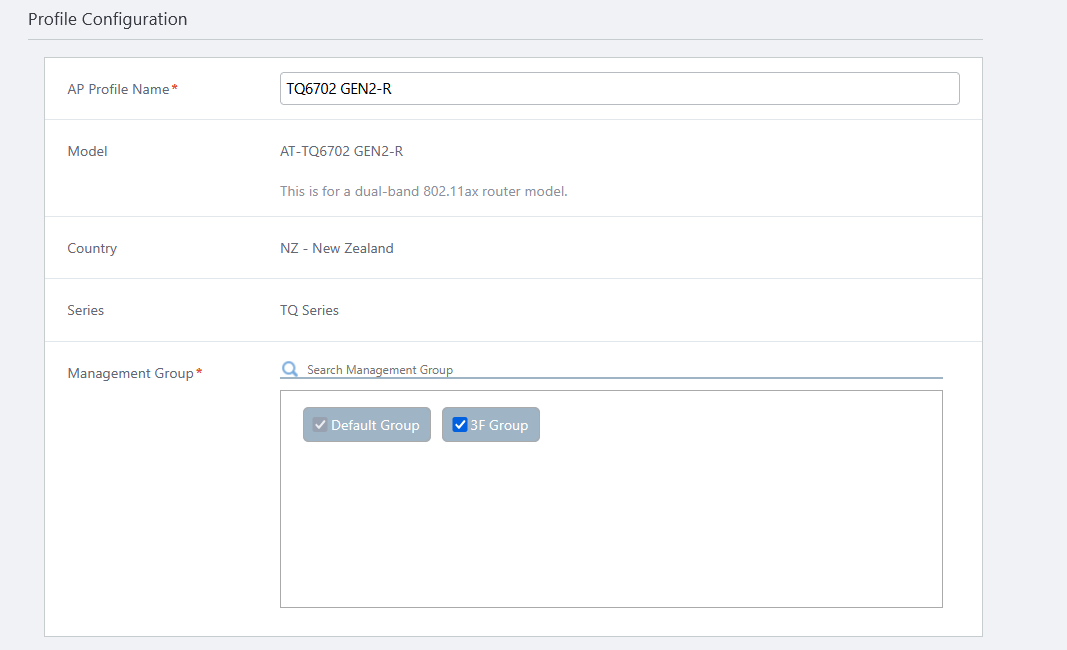
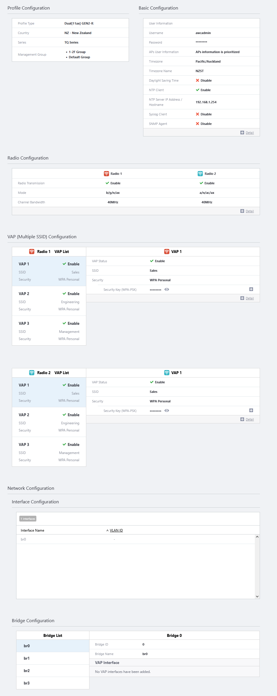
- Configure general parameters in the "Profile Configuration" section.
Enter "TQ6702 GEN2-R" in "AP Profile Name".
The "Model", "Country" and "Series" fields show the options selected in the earlier "Select Country, AP Series and Model" dialog box.
Select the Management Groups that you want this AP Profile to belong to.
An AP Profile can be used in multiple Management Groups by selecting those groups in this dialog box.
Note that you cannot uncheck the "Default Wireless Group".
- You can specify the AP's system settings in the "Basic Configuration" section.
If the Profile Model is "AT-TQ7403-R" or "AT-TQ6702 GEN2-R", you need to set an existing username and password for the AP to apply the AP Profile.
But even when the APs are under the AWC Plug-in's control, each AP's web interface is still accessible.
Be sure to change the username and password or create a new one for the AP's administrative account before using it, as the initial account allows a malicious client to enter the wireless AP's Web GUI and change the settings.
Note
You can also change the administrator account of an AP before adding it to the AWC Plug-in.
Note
If you configure the usernames and passwords in both the AP Profile and the AP-specific configuration on the same AP, the username and password in the AP-specific configuration will take effect.
Note
Here, we will apply the previously created admin account.If you specify a username and password for the AP's guest-class on a parent AMF Plus node, ensure that the AP's login username and password are the same as the ones configured for the guest-class.
If you want to manage an AP which was detected as a guest device under the AWC Plug-in, specify the same username and password that is configured for the AP's guest-class and AP's web interface.
If you want to use a different username and password for each AP, create a separate guest-class for each AP on the parent AMF Plus devices.
When managing multiple APs, different user information can be configured for each. In this case, set dummy user information in the AP Profile, assign it to the AP, and then set the appropriate user information for the individual APs in the Wireless AP Individual Configuration screen, and apply the settings.
This Quick Tour deals with only one AP, so set the actual user information directly to the AP Profile.
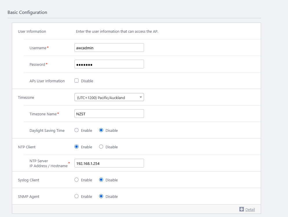
First, enter the "Username" and "Password" displayed in the "User Information" section.
- Username
Should be 1 to 64 characters in length, with alphabets (case-sensitive), numbers and symbols (! " # $ % & ' ( ) * + , - . / : ; < = > @ [ \ ] ^ _ ` { | } ~ may be used).
The password is case-sensitive.
Also note that the username must be started with alphabet, or the available symbols listed above, except a plus (+).
Here we enter the previously created username, "awcadmin".
- Password
Should be 1 to 32 characters in length, with alphabets (case-sensitive), numbers and symbols (! " # $ % & ' ( ) * + , - . / : ; < = > @ [ \ ] ^ _ ` { | } ~ may be used).
The password is case-sensitive.
Here we enter the previously created password, "naisho!".
- Username
- In the "Timezone" section, select a timezone to apply to the APs.
Here, we set the time display to NZST (New Zealand Standard Time). Select "(UTC+1200) Pacific/Auckland" from the drop-down list.
You can also narrow down the choices displayed in the drop-down list by entering a part of the above timezone character string in the search field above the drop-down list, such as "1200" or "Auckland" in this case.
In addition to the time zone selection above, enter "JST" in the Timezone Name field.
Once you select one of the time zones, additional item for "Daylight Saving Time" will appear. Here we leave "Disable" as default.
- The "NTP Client" field is used to enable/disable the NTP client on the APs.
To use the AWC (Autonomous Wave Control) feature, which we will describe later, you have to enable the NTP client.
When the AP is a member of an AMF Plus network, the time is automatically synchronized from the AMF Plus controller (or master if none exists), but this time we explicitly set "NTP Client" to "Enable" and designate the AMF Plus master (192.168.1.254) as the NTP server.
When you enable the NTP client, an additional "NTP Server IP Address/Hostname" field will appear. Enter the IP address of the AMF Plus master (192.168.1.254) that is configured as an NTP server.
- The "Syslog Client" field lets you enable or disable the syslog client feature on the APs.
If you want the APs to send log messages to the syslog server, enable this item.
Here we set the syslog client to disabled.
- You can enable or disable the SNMP agent on the APs in the "SNMP Agent" section.
If you want to monitor and configure the APs with SNMP manager, enable this item.
Here we set the syslog client to disabled.
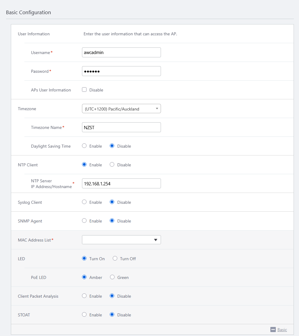
- Clicking "+ Detail" will show "MAC Address List", and "LED".
- "MAC Address List" lets you specify MAC address lists (blacklist or whitelist) used by MAC Access Control features with a MAC Address List on the APs.
An AP can use only a single MAC address list but the MAC Address List feature can be enabled or disabled per VAP (SSID).
Here we haven't created a MAC address list. Leave "MAC Address List" empty in order to accept all wireless clients that have a valid SSID and key.
- The "LED" field lets you select the operational mode of the AP's LEDs.
Here we choose "Turn On" for "LED".
As for TQ6702 GEN2-R, the color of the PoE LED when receiving PoE power can be selected from Amber and Green in the "PoE LED".
This time, we leave the "PoE LED" as its default, "Amber".
- When "STOAT" is enabled the AMF Plus Device Discovery feature is supported. Using STOAT (Standardized Topology Organizer and Transport), topology information acquired by the wireless AP function and MAC-based authentication function is notified to the STOAT collector, accumulated, and reflected in the Vista Manager EX network map.
When used in conjunction with MAC access control via RADIUS, the Intelligent Edge Security (IES) feature allows the Vista Manager EX to allow or deny connections from endpoints (client devices located at the end of the network).
This time, set "STOAT" to "Enable" so that the Vista Manager EX network map can reflect the topology information of connected wireless clients.
Note that the IES function is not available this time because MAC access control is not enabled.
- When "STOAT" is enabled, an additional item "STOAT Destination" will appear. The STOAT Destination setting is required in this version.
When "STOAT Destination" is enabled, the "IP Address/Hostname" and "Key" input fields will appear.
We assume that the AMF Plus master is already configured with the appropriate STOAT collector function, so we specify its IP address/hostname and password. Please set up according to the actual environment.
- "MAC Address List" lets you specify MAC address lists (blacklist or whitelist) used by MAC Access Control features with a MAC Address List on the APs.
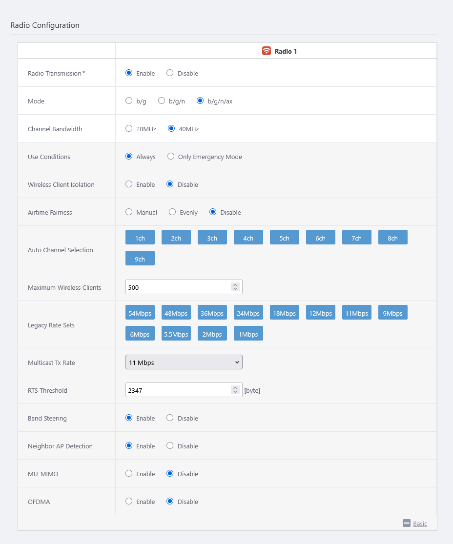
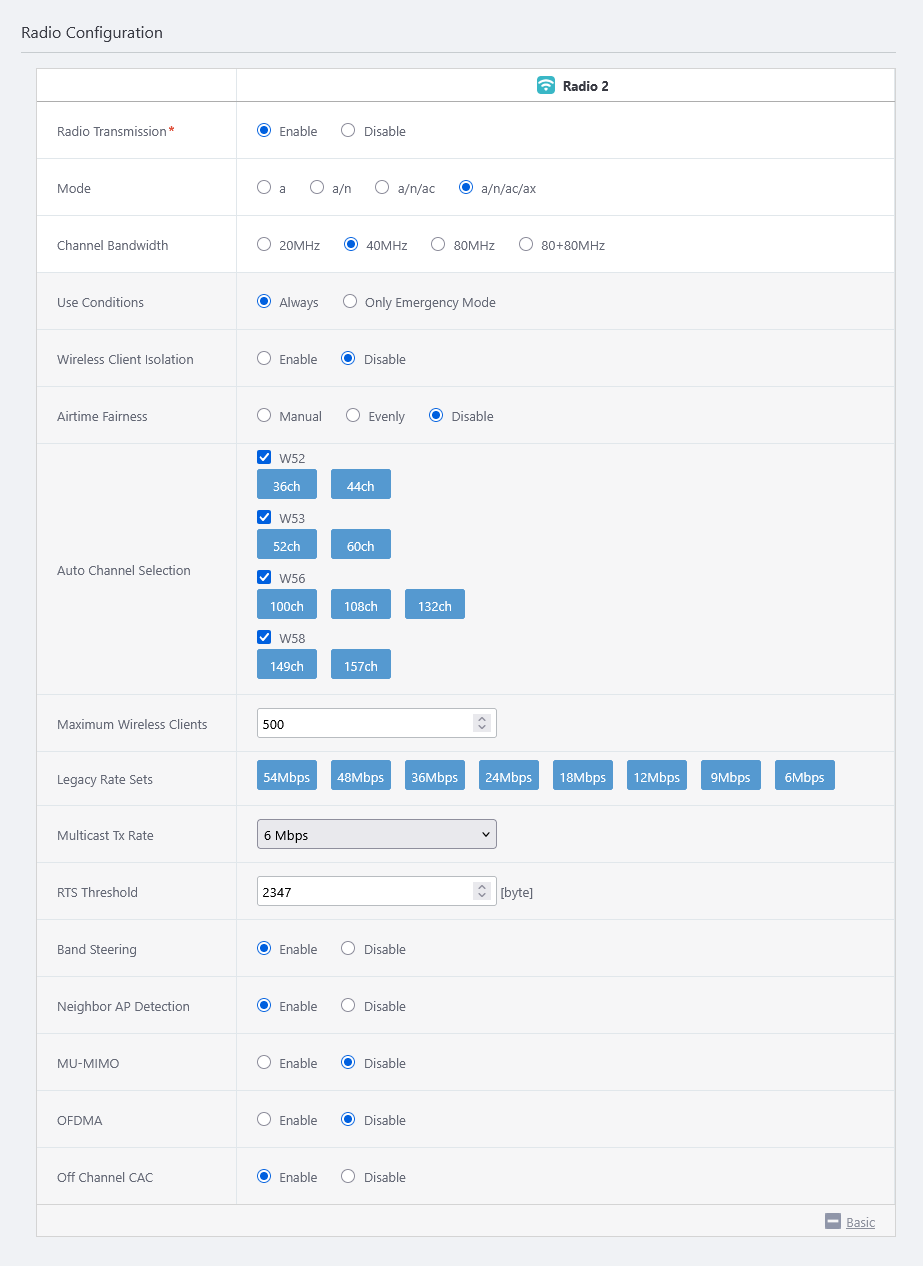
- You can specify configuration parameters for radio waves in the "Radio Configuration" section.
Depending on the selected model, configure "Radio 1 (2.4GHz)" and "Radio 2 (5GHz W52/W53/W56)" appropriately. You can switch the radio by clicking the "Radio 1" and "Radio 2" buttons at the top of the screen.
Here we enter the following data:
Table 1: TQ6702 GEN2-R Radio Configuration Item Name Value Description Radio 1 Radio 2 Radio Transmission Enable Enable Specify whether to transmit and receive radio waves in the selected frequency band. Mode b/g/n/ax a/n/ac/ax Specify the wireless modes (protocols) to use. Bandwidth 40MHz 40MHz Specify the bandwidth to use. IEEE 802.11ax, IEEE 802.11ac and IEEE 802.11n can aggregate two or four adjacent channels to make a large 40MHz or 80MHz channel. Use Conditions Always Always Select "Always" to always use the wireless feature. Select "Only Emergency Mode" to use the radio band only in emergency mode.
Refer to Enable Emergency Mode for more details.Wireless Client Isolation Disable Disable Specify whether to block communication between wireless clients connected to the same VAP. Airtime Fairness Disable Disable Specify whether to give each client an equal amount of airtime regardless of its speed. Auto Channel Selection All All Specify the channels to use. All channels are selected by default. Maximum Wireless Clients 500 500 Specify the maximum number of clients that can connect to the APs. Legacy Rate Sets All All Specify valid rates to use when IEEE 802.11b/g or IEEE 802.11a is being used. Multicast Tx Rate 11 Mbps 6 Mbps Specify a selection method for IEEE 802.3 multicast/broadcast rate. RTS Threshold 2347 2347 To transmit RTS packets in IEEE 802.11b/g/a mode, select Enable and specify the minimum size of Tx packets. Band Steering Disable Disable Specify whether to use the Band Steering feature, which encourages clients supporting both 2.4GHz and 5GHz to prefer 5GHz in order to reduce congestion in 2.4GHz.
The setting of this item is set a common value to both "Radio 1" and "Radio 2". Also, when using this feature, please set the SSID and Security to the same for each VAP of Wireless 1 and Wireless 2.Neighbor AP Detection Enable Enable Specify whether to detect rogue APs in the radio band.
When enabled, APs detect the radio waves of wireless APs managed/unmanaged by the AWC Plug-in that use the same wireless band nearby, and reflects them in Wireless IDS/IPS and AWC calculations.
If you disable this, these functions may not work properly.MU-MIMO Disable Disable Select whether to Enable or Disable MU-MIMO (Multi-user MIMO).
MU-MIMO allows multiple wireless clients to communicate simultaneously (upwards and downwards), thus increasing the communication speed.
Note
This item is displayed when a mode containing "ac" or "ax" is selected for the Radio Configuration.
OFDMA Disable Disable Select whether to Enable or Disable OFDMA (Orthogonal Frequency Division Multiple Access).
OFDMA allows multiple wireless clients to communicate simultaneously by dividing the channel into multiple RUs (resource units).
Note
This item is displayed when a mode containing "ax" is selected for the Radio Configuration.
Zero wait DFS - Enable Specify whether to use Zero wait DFS.
When the Zero Wait DFS function is set "Enable", the system constantly monitors the candidate channel to be changed when a waveform that is considered as from a weather radar is detected, and immediately switches to the candidate channel once radar is detected.
Note
This setting appears only when AP Model is selected as "AT-TQ6702 GEN2-R" and Radio Band as "Radio 2".
◼ Radio 1
◼ Radio 2
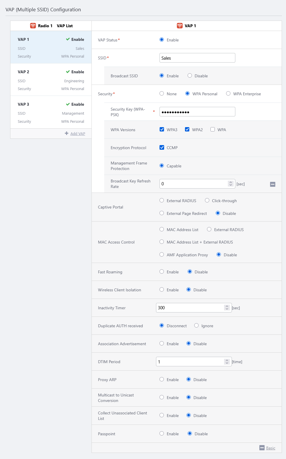
- Configure VAPs in the "VAP (Multiple SSID) Configuration" section.
Here, we will create SSIDs "Sales", "Engineer", and "Management" for each radio band.
In all cases, security is set to WPA Personal and version to WPA2/WPA3.
In this case, we will use the defaults, as we will not be using any of the other features.
- Radio 1
Table 2: TQ6702 GEN2-R VAP (Multiple SSID) Configuration Radio 1 Item Name Value Description Radio 1 VAP 1 Radio 1 VAP 2 Radio 1 VAP 3 VAP Status Enable Enable Enable Specify one of "Enable", "Disable" and "Emergency". The VAP Status of VAP1 is always "Enable" when "Use Condition" in the "Radio Configuration" section is set to "Always". SSID Sales Engineer Management Specify an SSID (network name) to use on the VAP. Broadcast SSID Enable Enable Enable Specify whether to broadcast the SSID on the VAP. Security WPA Personal WPA Personal WPA Personal Specify a security method for the VAP. Security Key (WPA-PSK) Passphrase1 Passphrase2 Passphrase3 Specify an encryption key for the VAP. WPA Versions WPA3 / WPA2 WPA3 / WPA2 WPA3 / WPA2 Specify a WPA version to use on the VAP. Encryption Protocol CCMP CCMP CCMP Specify an encryption protocol to use on the VAP. Management Frame Protection Capable Capable Capable Specify whether to protect management frames. Broadcast Key Refresh Rate 0 0 0 Specify an interval at which to refresh the broadcast key that is sent to clients on the VAP. Specifying "0" stops the key from refreshing. Captive Portal Disable Disable Disable Specify whether to use the Captive Portal feature on the VAP. MAC Access Control Disable Disable Disable Specify whether to use MAC Access Control on the VAP. Fast Roaming Disable Disable Disable Specify whether to use Fast Roaming of wireless clients. Inactivity Timer 300 300 300 Specify the delay before disconnecting a client that disappears without notifying the APs. Duplicate AUTH received Disconnect Disconnect Disconnect Select how to process connection requests from clients that have maintained a connection. Association Advertisement Disable Disable Disable Specify whether to use Association Advertisement. DTIM Period 1 1 1 Specify how frequently to insert a DTIM (Delivery Traffic Indication Map) in the AP's beacons (every 1 to 255 beacons). Proxy ARP Disable Disable Disable Specify whether to use Proxy ARP. Multicast to Unicast Conversion Disable Disable Disable Specify whether to convert multicast packets to unicast packets. Collect Unassociated Client List Disable Disable Disable Specifies whether or not to obtain a list of unregistered endpoints that have failed to authenticate to the RADIUS server in IES (Intelligent Edge Security). Passpoint Disable Disable Disable Specify whether to use Passpoint (Hotspot 2.0).
◼ Example of VAP 1
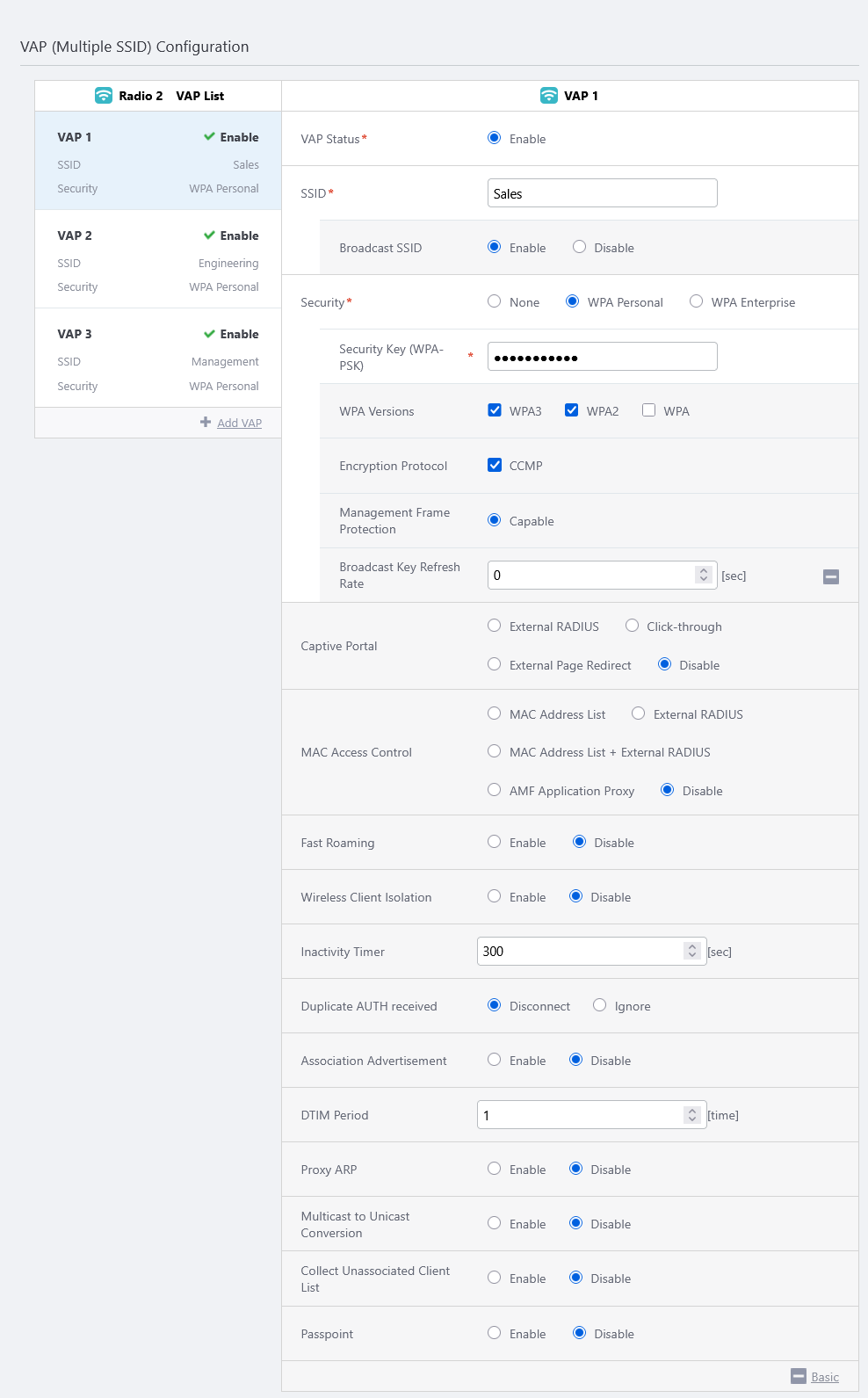
- Radio 2
Table 3: AT-TQ6702 GEN2-R VAP (Multiple SSID) Configuration Radio 2 Item Name Value Description Radio 2 VAP 1 Radio 2 VAP 2 Radio 2 VAP 3 VAP Status Enable Enable Enable Specify one of "Enable", "Disable" and "Emergency". The VAP Status of VAP1 is always "Enable" when "Use Condition" in the "Radio Configuration" section is set to "Always". SSID Sales Engineer Management Specify an SSID (network name) to use on the VAP. Broadcast SSID Enable Enable Enable Specify whether to broadcast the SSID on the VAP. Security WPA Personal WPA Personal WPA Personal Specify a security method for the VAP. Security Key (WPA-PSK) Passphrase1 Passphrase2 Passphrase3 Specify an encryption key for the VAP. WPA Versions WPA3 / WPA2 WPA3 / WPA2 WPA3 / WPA2 Specify a WPA version to use on the VAP. Encryption Protocol CCMP CCMP CCMP Specify an encryption protocol to use on the VAP. Management Frame Protection Capable Capable Capable Specify whether to protect management frames. Broadcast Key Refresh Rate 0 0 0 Specify an interval at which to refresh the broadcast key that is sent to clients on the VAP. Specifying "0" stops the key from refreshing. Captive Portal Disable Disable Disable Specify whether to use the Captive Portal feature on the VAP. MAC Access Control Disable Disable Disable Specify whether to use MAC Access Control on the VAP. Fast Roaming Disable Disable Disable Specify whether to use Fast Roaming of wireless clients. Inactivity Timer 300 300 300 Specify the delay before disconnecting a client that disappears without notifying the APs. Duplicate AUTH received Disconnect Disconnect Disconnect Select how to process connection requests from clients that have maintained a connection. Association Advertisement Disable Disable Disable Specify whether to use Association Advertisement. DTIM Period 1 1 1 Specify how frequently to insert a DTIM (Delivery Traffic Indication Map) in the AP's beacons (every 1 to 255 beacons). Proxy ARP Disable Disable Disable Specify whether to use Proxy ARP. Multicast to Unicast Conversion Disable Disable Disable Specify whether to convert multicast packets to unicast packets. Collect Unassociated Client List Disable Disable Disable Specifies whether or not to obtain a list of unregistered endpoints that have failed to authenticate to the RADIUS server in IES (Intelligent Edge Security). Passpoint Disable Disable Disable Specify whether to use Passpoint (Hotspot 2.0).
◼ Example of VAP 1
- Radio 1
- In the Bridge Settings of the Network Configuration, create bridges br1, br2, and br3 according to the settings made for the AT-TQR series from the CLI.
◼ br1
To begin, configure br1 and the corresponding VAP interfaces for VAP 1 in Radio 1/2.
- First, click "Add Bridge" in the bridge list to add a bridge configuration field.
- Enter "1" to "Bridge ID". Bridge name will be updated to "br1".
- Click "Add VAP Interface" to add a VAP interface configuration field.
- Set "Radio" to "Radio 1", and "VAP" to "1".
- Click "Add VAP Interface" again to add another VAP iterface configuration field.
- This time, set "Radio" to "Radio 2", and "VAP" to "1".
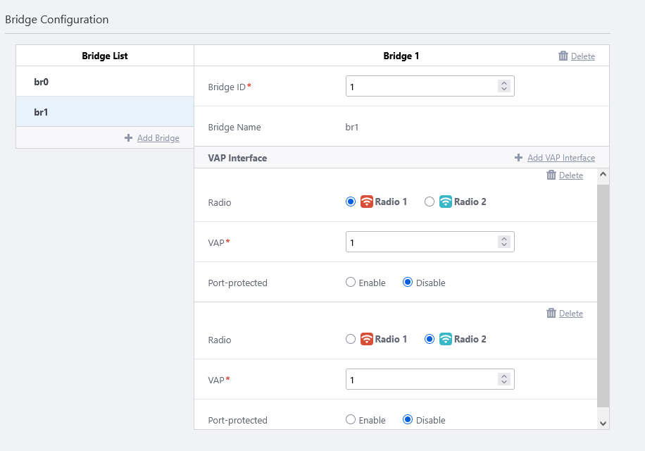
When applying this AP Profile to the TQR series later, the 802.1Q Ethernet sub-interface eth1.10, which has already been assigned to bridge group 1 from the CLI, will be able to communicate with the VAPs "Sales" on Radio 1 and 2.
Untagged packets on the VAP interface are tagged with VLAN ID 10 when forwarded to eth1.10. Packets with a tag of VLAN ID 10 arriving from outside to eth1 will be forwarded as untagged packets to the VAPs "Sales" on the VAP interfaces.
◼ br2 and br3
In the same way, assign VAP 2 for Radio 1 and 2 to bridge br2, and VAP 3 for Radio 1 and 2 to bridge br3.
When applying this AP Profile to the TQR series later, the 802.1Q Ethernet sub-interface eth1.20, which has already been assigned to bridge group 2 from the CLI, will be able to communicate with the VAPs "Engineer" on Radio 1 and 2, and the 802.1Q Ethernet sub-interface eth1.100 assigned to bridge group 3, will be able to communicate with the VAPs "Management" on Radio 1 and 2.
Untagged packets on VAP "Engineer" on Radio 1/2 are tagged with VLAN ID 20, and untagged packets on VAP "Management" are tagged with VLAN ID 100 and sent from eth1. Also, packets with tags of VLAN ID 20 and 100 arriving from outside to eth1 are forwarded as untagged packets to VAP "Engineer" and "Management", respectively.
- First, click "Add Bridge" in the bridge list to add a bridge configuration field.
- Click "Add" at the top right of the screen.
The settings of the AP Profile "TQ6702 GEN2-R" will be displayed.
Register AP
Register the wireless AP router under the control of the AWC Plug-in.When registering the wireless router to the AWC plug-in, only IP manual configuration is supported. Automatic configuration via DHCP is not supported.
Also be noted that the wireless router can be an AMF Plus node, but not an AMF Plus guest node, thus the AWC Plug-in cannot detect the wireless router from the AMF Plus guest node information.
NoteWhen registering the AT-TQR series under the management of the AWC Plug-in, use only eth1 for connection to the AMF Plus network. If you try to connect to the AMF Plus network via eth2, you will not be able to register under the control of the AWC Plug-in.
From the "AP Settings" screen, select "Manual Registration" and specify the IP address and MAC address of the TQ6702-GEN2-R.
- Select "Wireless Configuration" > "AP Settings" from the AWC Plug-in menu.
The AP list screen will appear.
- Place the mouse cursor on the gear icon at the top right of the screen and select "Manual Registration" from the submenu.

The "Wireless AP Registration" dialog box will appear.
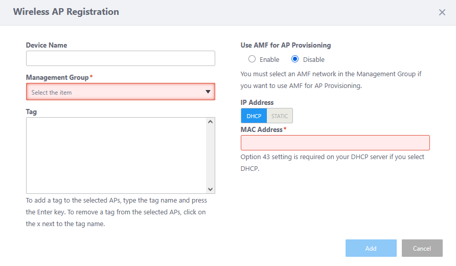
- Enter an administrative name for the AP you want to register, in the "Device Name" field.
Here we enter the name "TQR-3F-1".
- Specify the Management Group that you want the AP to belong to.
If "AMF Network" and "AMF Area" are selected in the pre-created management group, "Enable" will be displayed as the option for Use AMF for AP Provisioning.
- Select Enable or Disable in "Use AMF for AP Provisioning".
- If "Use AMF for AP Provisioning" is disabled, the AWC Plug-in requires the AP's IP and MAC addresses for management.
In this case, you have to preconfigure the AP's IP address via its management web interface, or assign the one via DHCP.
Note
When registering the wireless AP router to the AWC Plug-in, only manual IP configuration is supported; IP address assignment by a DHCP server is not available.
- If "Use AMF for AP Provisioning" is enabled, the AWC Plug-in can detect conventional wireless APs by using the AP's AMF Plus guest device information (AMF Plus network area, parent device, and the port to which the AP is connected). However, the wireless AP router cannot be an AMF Plus guest node, therefore cannot be detected this way.
- If "Use AMF for AP Provisioning" is disabled, the AWC Plug-in requires the AP's IP and MAC addresses for management.
- Specify the "IP Address" of the AP "TQR-3F-1".
If you know the AP's IP address in advance, because you have statically configured the AP's IP address via its interface or you have set up a DHCP server to statically assign the IP address to the AP's MAC address, select "STATIC" and enter the IP address of the AP.
If you want a DHCP server to assign an IP address to the AP via the AWC Plug-in dynamically, select "DHCP".
As we already know that "TQR-3F-1" has a statically configured IP address "192.168.1.200", here we select "STATIC" and enter "192.168.1.200".
- Enter the "MAC Address" of the AP to be added as "TQR-3F-1".
Here we enter a MAC address of "00:00:5e:00:53:00".
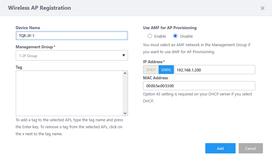
- Click "Add".
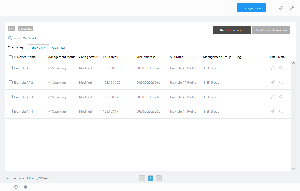
The "Wireless AP Detail" screen will appear.
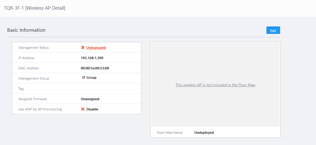
- Now you can see the newly added AP "TQR-3F-1". At this stage, the "Management Status" is "Unmanaged" and the "AP Profile" is "Unconfigured".
With the "Wireless AP Detail" screen open, move on to the next section, "Apply AP Profile".
Apply AP Profile
- In "Wireless AP Detail", click on the "Configuration" tab and display the Configuration details.
- Click "Edit" button at the top right-hand corner of the "Wireless AP Individual Configuration".
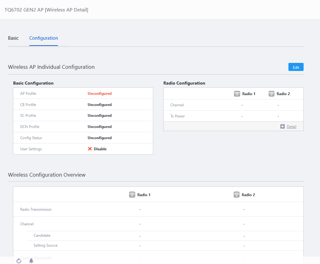
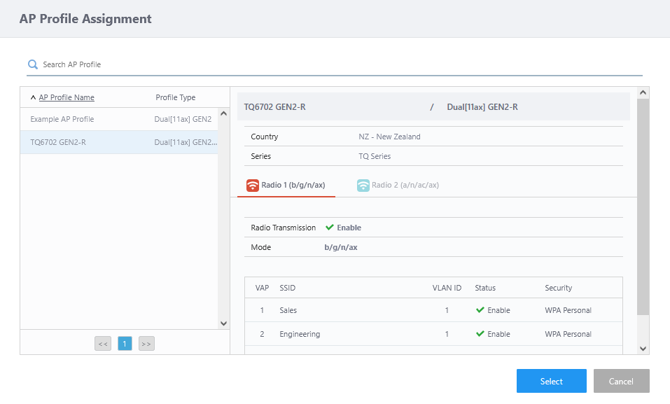
The "AP Profile Assignment" dialog box will appear.
- Select an AP Profile from the profile list on the left side.
Here we select "TQ6702 GEN2-R" and click "Select".
The "Wireless AP Individual Configuration" page will appear.
The "Wireless AP Individual Configuration" screen allows selection of a AP Profile, as well as User information settings, Interface Configuration, Radio Configuration, and WDS Configuration for the individual AP.
Since only one AP will be set up this time, the User Configuration of the individual AP have not been changed.
Also, other settings will not be performed at this time.
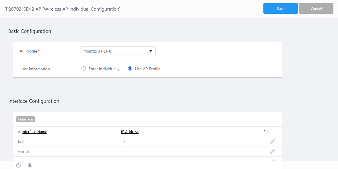
- Click "Save".
The "Wireless AP Detail" screen will appear. The "Management Status" displays "Searching" and the "AP Profile" displays "TQ6702 GEN2-R" selected in the above procedure.
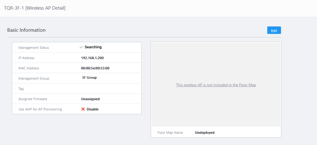
Usually, the management status will change to "Applying" or "Managing" when you return to the "AP Settings" screen again after a while.
NoteWhen the channel of the TQR series wireless AP under AWC plug-in management is set to "Auto" and if the channel/transmit power is changed after the AWC calculation and application of the calculation results, the channel/transmit power in the Running Config/Startup Config of the wireless AP in question will not show "auto" but the applied channel/transmit power will be displayed.
The settings are reflected in the Running Config/Startup Config at the time when the automatic polling of the AWC, which takes place every hour at 0, 15, 30, and 45 minutes, is executed.
10 Nov 2025 11:49