3D Floor Map [Associated Client View]
On the 3D Floor Map view, select "Associated Client View" from the View Selection dropdown menu to display the information of the associated clients on the currently selected floor maps.
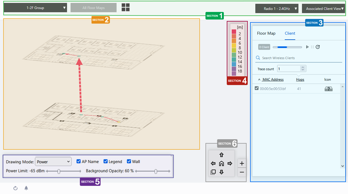
Section 1
| Item Name | Description |
|---|---|
| Management Group drop-down menu | You can narrow down the floor map to be displayed. If you change the currently selected management group, the 3D Floor Map view will be canceled and you will return to the Floor Map List panel view. |
| Floor Map drop-down menu | Disabled on 3D floor map. |
| "Back to list" button |
Click to return to the Floor Map List screen. |
| Radio dropdown menu | Lets you select a radio band to show on the map from following options:
|
| View Selection dropdown menu | Lets you change what information is displayed on the Floor Map Details screen.
|
Section 2
The selected floor map will be displayed layer by layer.
The display angle of the floor maps can be controlled using the angle adjustment button at the bottom right.
Each floor map displays the icons of the wireless APs you have placed on the individual floor map detail screens.
You can view the estimated location of the selected wireless client in the client list on the right side of the content section. For the estimated location of a wireless client, you can also view the path it has traveled in the recent past or over a specified period.
Section 3
Floor maps / wireless client list will be displayed. You can switch between the floor map list and the wireless client list using the tabs at the top of the list.
Place the mouse pointer on any line in the floor map list to highlight the corresponding floor map in the layered view.
| Item Name | Description |
|---|---|
| Header | |
| Floor Map/Client Tab | Switches the contents of the list. |
| Floor Map List | |
| X Deployment Map | Displays the number of floor maps that belong to the selected management group. |
| Refresh Timer | Shows the status of the timer that automatically refreshes the page with the blue progress bar. In the 3D floor maps view, the resume/pause automatic update buttons and the manual update button are displayed along with a progress bar. By default, automatic updates are paused. |
| Search Floor Map | Disabled on 3D floor map. |
| Checkbox | Check this box if you want to select the floor map as the display target. |
| Floor Map | The floor map names belonging to the selected management group will be displayed. |
| Origin | Displays the upper left coordinate of the floor map image. |
| Height | Displays the set ceiling height of the floor. |
| Order | You can change the order of the floor map by clicking and holding the mouse pointer up or down. |
| Edit (pencil icon) | The "Edit 3D Map Settings" dialog box will appear. ◼ Edit 3D Map Settings 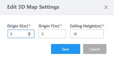
|
| Client list | |
| X Client | Displays the number of wireless clients connected to the wireless AP, or the number of wireless clients that have a history of connecting to the wireless AP during the specified period. |
| Refresh Timer | Shows the status of the timer that automatically refreshes the page with the blue progress bar. In the 3D floor maps view, the resume/pause automatic update buttons and the manual update button are displayed along with a progress bar. By default, automatic updates are paused. |
| Search Associated Clients | You can search for clients that are currently connected to the AP or have a history of connecting to the AP during the specified period. Displays the items among the current display targets that contain the string entered in this field in the "MAC Address" field. To remove the filter, delete the string from the search field and press enter. NoteThe search is case-sensitive. |
| Trace count | Specifies the number of client movement histories to be reflected in the flow lines on the floor map. In the case of wireless clients whose location is estimated by Location Estimation, the floor map will reflect the estimated location for the specified number of times from the history of location estimation performed. Only wireless clients with Location Estimation results are displayed in the movement path. |
| Specified period | Check this box if you want to specify a specific period of the location estimation history or connection history to be displayed on the floor maps. When checked, you can specify the start and end date and time of the specified period using the calendar control or manually. Specify the period and click the "Search" button to reflect it in the list. |
| Checkbox | Select a wireless client to display its estimated location or associated wireless APs on the floor map. |
| MAC Address | Shows the MAC address of the wireless client. |
| Hops | Displays the hop count of the wireless client. For wireless clients whose connection location is estimated by Location Estimation, specify the number of times the location estimation is performed for each wireless client on the floor map. Only the specified number of the most recent hops will be displayed for each client. |
| Icon | Displays the wireless client icon shown on the floor map.
|
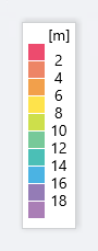
Section 4
Shows the legend for the Associated Client View.
The color of each cell in the legend represents the reliability of the location estimation of clients shown on the map.
The legend can be made invisible or visible by using a checkbox in the floor map control section at the bottom of the page.
Section 5

The Drawing Mode and Power Limit are disabled in the Associated Client View of the 3D floor maps.
| Item Name | Description |
|---|---|
| Wireless AP Name | Whether to display the AP name above the AP icon. Check to display. |
| Legend | Lets you enable or disable the legend. Check to display. |
| Wall | Lets you choose whether to display the walls if walls have been created on the floor map (using the Edit Wall page). Check to display.NoteIf walls have been defined, attenuation by the walls takes effect over the heat map even if this control is left unchecked. |
| Opacity | Specify the opacity of the floor map background image. |
Section 6
Adjusts the display size and angle of the map.
- Zoom In/Out buttons
You can zoom in (+) or zoom out (-) of the floor map display. You can also use the mouse wheel scroll to zoom in or out.

- Angle adjustment button
Only in the layered view, the angle at which the floor map is displayed can be adjusted using the arrow buttons.
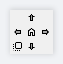
- Up/Down arrows: Adjust the vertical (pitch) angle.
- Left/Right arrows: Adjust the horizontal rotation (yaw) angle.
- Plan view button (left-bottom): All floors are superimposed and displayed as a plan view looking down from above.
- Home position (center): Returns the angle of view to the initial state.
- Up/Down arrows: Adjust the vertical (pitch) angle.
10 Nov 2025 11:49