Allied Telesis Container Platform
This section explains each setting page of the Allied Telesis Container Platform.
Dashboard
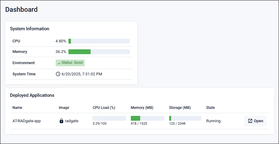
Allied Telesis Container Platform > DashboardThe Dashboard page is displayed immediately after logging in to the Allied Telesis Container Platform. It displays system information for the Allied Telesis Container Platform and lists installed applications (below is an example of the Dashboard page).
System Information
Displays system information for the Allied Telesis Container Platform.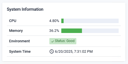
| CPU | Displays the CPU usage. |
| Memory | Displays the memory usage. |
| Environment | Displays the status of the Allied Telesis Container Platform. |
| System Time | Displays the time on the Allied Telesis Container Platform. |
Deployed Applications
AT-RADgate Displays the application's CPU usage, memory usage, etc.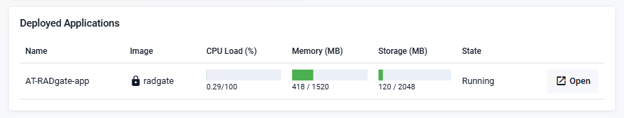
| Name | AT-RADgate-app (AT-RADgate application) |
| Image | Displays whether the application files are correct. |
| CPU Load (%) | Displays the CPU usage. |
| Memory (MB) | Displays the memory usage. |
| Storage (MB) | Shows storage usage. |
| Status | Displays the application status. |
| "Open" button | Click to launch the application. It is not displayed when "Status" is "Stopped". |
Network Infrastructure
Allied Telesis Container Platform > Network InfrastructureThis section explains the items that can be set in the "Network Infrastructure" menu.
Interface Management
Allied Telesis Container Platform > Network Infrastructure > Interface ManagementYou can check the interface status and change the settings.
The Allied Telesis Container Platform interface refers to the virtual machine network interface created in the Installation > Installing AT-RADgate procedure.
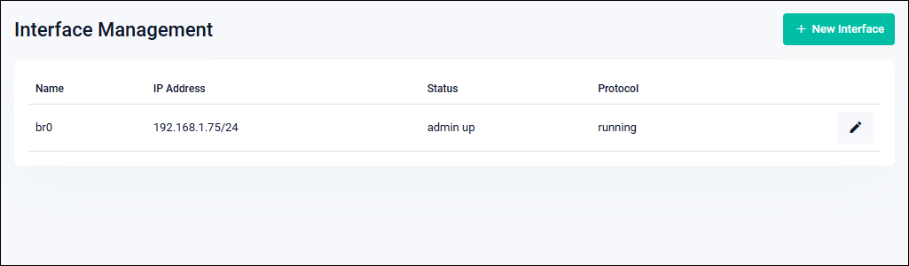
| Name | The interface name is displayed. |
| IP Address | A list of IPv4 Addresses configured for the interface is displayed. Secondary IP Addresses are displayed with the string "(Secondary)". |
| Status | Displays the administrative state of the interface. |
| Protocol | The link status of the interface is displayed. |
| "New Interface" button | This opens the New Interface dialog for adding a new interface. |
| "Pencil icon (Edit)" button | This opens the Edit Interface dialog, allowing you to change the interface settings. |
New Interface
An "802.1Q Ethernet subinterface" can be added to the interface to send and receive tagged packets with the VID specified by "VLAN ID".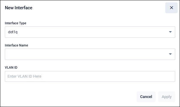
| Interface Type | "dot1q" is displayed. |
| Interface Name | Select the interface to be used as an untagged port. |
| VLAN ID | Enter the VLAN ID. |
| "Cancel" button | Return to the Interface Management page without adding an interface. |
| "Apply" button | Add the interface and return to the Interface Management page. |
Edit Interface
This is a dialog for modifying the settings of the specified interface.When the Edit Interface dialog appears, first select the address configuration method.
Based on the selected configuration method, the corresponding settings are displayed. Enter or select the required items, then click the "Apply" button to modify the interface settings.
If you click the "Cancel" button, you return to the Interface Management page without changing the settings.
The following section explains the input and selection items for each method.
Use DHCP
Select this method when obtaining the interface's IPv4 Address via DHCP.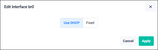
| Use DHCP | Select "Use DHCP" when obtaining an IPv4 Address from a DHCP server. |
| "Cancel" button | Return to the Interface Management page without changing the settings. |
| "Apply" button | Return to the Interface Management page after changing the settings. |
Fixed
Select "Fixed" when manually configuring the interface's IPv4 Address.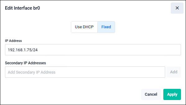
| Fixed | Select "Fixed" when manually configuring the IPv4 Address. |
| IP Address | Enter the IPv4 Address to set for the target interface in the format 192.168.101.1/24. Clicking the "Apply" button with an empty (undefined) field deletes the IPv4 Address for the corresponding interface. |
| Secondary IP Addresses | To set a secondary (additional) address, click "Add" button and enter the IP Address. |
| "Cancel" button | Return to the Interface Management page without changing the settings. |
| "Apply" button | Return to the Interface Management page after changing the settings. |
Static Routing
Allied Telesis Container Platform > Network Infrastructure > Static Routing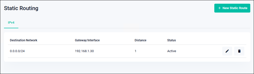
| Destination Network | The destination network address of the route is displayed. |
| Gateway/Interface | Displays the next-hop address or the outgoing interface for packets destined to the corresponding route. |
| Distance | Displays the administrative distance of the route entry. |
| Status | Displays the status of the route entry. |
| "New Static Route" button | The New Static Route dialog opens to add a static route. |
| "Pencil icon (Edit)" button | The Edit Static Route dialog opens to modify a static route. |
| "Trash icon (Delete)" button | Deletes the static route. A confirmation dialog appears before deletion. |
New Static Route
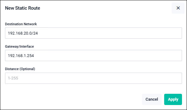
| Destination Network | Enter the destination network address for the route in the format 192.168.20.0/24.NoteIPv6 format is not supported. |
| Gateway/Interface | Enter the next-hop address for packets destined to the corresponding route in the format 192.168.1.254.NoteIPv6 and Interface input are not supported. |
| Distance (Optional) | Enter the administrative distance of the route entry. If omitted, the value defaults to 1, which is the default for static routes. |
| "Cancel" button | Returns to the Static Routing page without adding a route entry. |
| "Apply" button | Adds a route entry and returns to the Static Routing page. |
Edit Static Route

| Destination Network | Enter the destination network address for the route in the format 192.168.20.0/24.NoteIPv6 format is not supported. |
| Gateway/Interface | Enter the next-hop address for packets destined to the corresponding route in the format 192.168.1.254.NoteIPv6 and Interface input are not supported. |
| Distance (Optional) | Enter the administrative distance of the route entry. If omitted, the value defaults to 1, which is the default for static routes. |
| "Cancel" button | Return to the Static Routing page without modifying the route entry. |
| "Apply" button | Modify the route entry and return to the Static Routing page. |
Bonding
Allied Telesis Container Platform > Network Infrastructure > BondingYou can configure interface bonding (redundancy).
NoteUp to two ports are supported for interface bonding.
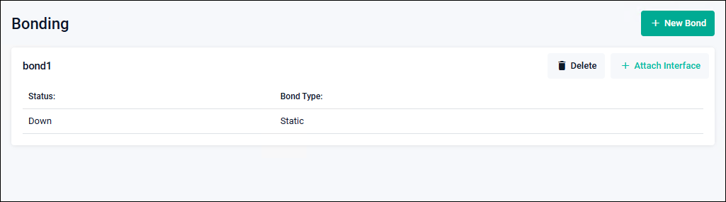
| Status | Displays the administrative state of the interface. |
| Bond Type | "Static" or "LACP" is displayed. |
| Member | Interfaces that belong to the bond are displayed. |
| "Attach Interface" button | The Attach Interface dialog opens to add an interface to the bond. |
| "Delete" button | Delete the bond. A confirmation dialog appears before deletion. |
| "Trash icon (Delete)" button | Delete a network port that belongs to the bond. |
| "New Bond" button | The New Bond dialog opens to create a bond. |
New Bond
Create a bond.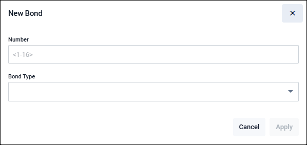
| Number | Enter the bond number. |
| Bond Type | Select either "Static" or "LACP". |
| "Cancel" button | Return to the Bonding page without modifying the settings. |
| "Apply" button | Add a bond and return to the Bonding page. |
Attach Interface
Configure the interfaces for redundancy.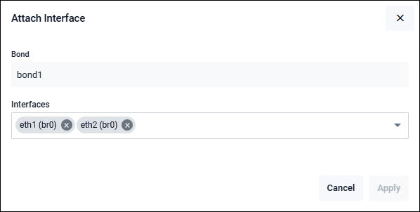
| Bond | The bond number is displayed. |
| Interfaces | Add an interface to the bond. |
| "Cancel" button | Return to the Bonding page without modifying the settings. |
| "Apply" button | Add an interface to the bond and return to the Bonding page. |
Interface Bonding Procedure
This section provides a simplified procedure for interface bonding.Depending on the configuration, you may not be able to access the Allied Telesis Container Platform settings page. Please be aware of this.
| bondx | Displays the created bondx port. (x represents the bond number.) |
| eth port (belongs to br0) | Indicates that the eth port is bridged (belongs to "br0"). |
It is also acceptable to add the eth port (belonging to br0) that connects to the Allied Telesis Container Platform in this procedure.
- Create bondx on the Bonding page.
- Assign bondx to the bridge on the Bridging page.
- Assign an eth interface to bondx on the Bonding page.
Note
When adding a bonding interface, if you add the eth port that connects to the Allied Telesis Container Platform to access its settings page, it takes approximately 10 seconds for the settings to be applied. Please proceed to the next operation after the settings have been applied. Proceed to the next operation after the settings have been applied.
- Connect the cable.
In this procedure, note that adding the eth port (belonging to br0) that connects to the Allied Telesis Container Platform makes it impossible to access the settings page of the Allied Telesis Container Platform.
- Create bondx on the Bonding page.
- Assign an eth interface to bondx on the Bonding page.
Note
When the eth port (belonging to br0) that connects to the Allied Telesis Container Platform is added, it is removed from the bridge, and access to the settings page of the Allied Telesis Container Platform becomes unavailable.
Therefore, when adding a bonding interface, do not include the eth port that is connected for accessing the settings page. - Assign bondx to the bridge on the Bridging page.
- Connect the cable.
- Create bondx on the Bonding page.
- Assign an eth interface to bondx on the Bonding page.
- Set an IP Address for bondx on the Interface Management page.
- Connect the cable.
Bridging
Allied Telesis Container Platform > Network Infrastructure > BridgingYou can change the member ports of the VLAN-capable software bridge "br0" and modify the VLAN settings assigned to the member ports.
By default, all network ports belong to the bridge as untagged ports of vlan1, but it is also possible to remove specific ports from the bridge to use them as standalone ports, or to change their VLAN membership and tag settings within the bridge.
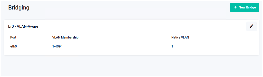
| Port | The names of network ports belonging to the bridge are displayed. |
| VLAN Membership | The VLAN ID to which the corresponding port belongs is displayed. |
| Native VLAN | The native VLAN ID (untagged VLAN ID) of the corresponding port is displayed. |
| "New Bridge" button | Not supported. Do not use it. |
| "Pencil icon (Edit)" button | Display the Edit Bridge dialog to add, remove, or modify bridge member ports. |
Edit Bridge
Display the "Bridge Edit" dialog to add, remove, or modify bridge member ports.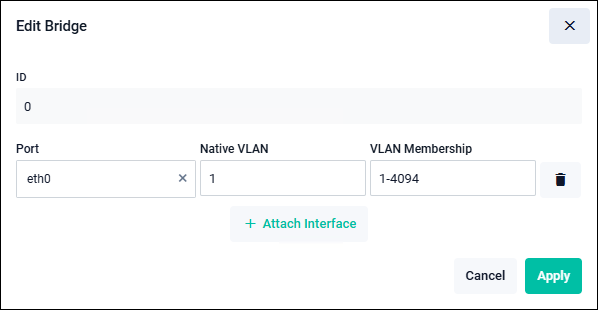
| ID | Bridge number "0" is displayed. |
| Port | Member ports are displayed. If a replaceable port exists, you can click "×" and then select a new port. |
| Native VLAN | The VLAN ID treated as "untagged" for the corresponding port is displayed. To make changes, specify a single value (e.g., 1) from the range of VLANs to which you belong. Untagged packets received on the corresponding port are handled as part of the native VLAN. Packets belonging to the native VLAN are transmitted without tags. When multiple VLANs are assigned, VLANs other than the native VLAN are tagged. |
| VLAN Membership | The VLAN ID to which the corresponding port belongs is displayed. To modify the setting, specify a single value (e.g., 1) or a range (e.g., 1–4094) from within the VLAN range of 1 to 4094. |
| "Trash icon (Delete)" button | Remove the corresponding port from the bridge. |
| "Attach Interface" button | This is used to add a port to the bridge. An input field is added. Select the port to add, and enter the assigned VLAN and native VLAN as needed. |
| "Cancel" button | Discard changes (such as adding, deleting, or modifying ports) made in the Edit Bridge dialog and return to the Bridging page. |
| "Apply" button | Apply the changes (such as adding, deleting, or modifying ports) made in the Edit Bridge dialog and return to the Bridging page. |
Example Configuration: Default Operation
The initial settings on the Interface Management page and the Bridging page are as follows.| br0 | 192.168.1.1/24 (default value when no DHCP server is present on the network) |
| Port | eth0 to ethx |
| VLAN Membership | 1 |
| Native VLAN | 1 |
Configuration Example: Accessing the Allied Telesis Container Platform management page using VLAN ID 100 with tagged communication
On the Interface Management page, add an “802.1Q Ethernet subinterface” to br0 with VLAN ID 100.| br0 | 192.168.1.1/24 |
| br0.100 | 192.168.100.1/24 |
| Port eth0 | |
| VLAN Membership | 1-100 |
| Native VLAN | 1 |
| Ports eth1 to ethx | |
| VLAN Membership | 1 |
| Native VLAN | 1 |
Access to the Allied Telesis Container Platform management page from ports 1 to x is available only via VLAN ID 1 with untagged communication.
Configuration Example: Using an application with VLAN ID 100 and tagged communication
| br0 | 192.168.1.1/24 |
| Port eth0 | |
| VLAN Membership | 1-100 |
| Native VLAN | 1 |
| Ports eth1 to ethx | |
| VLAN Membership | 1 |
| Native VLAN | 1 |
| Interface Type | Virtual |
| External Network VLAN ID | 100 |
| IPv4 Address | 192.168.100.2/24 |
| Gateway Address | 192.168.100.254/24 |
Ports 1 to x do not allow access to the AT-RADgate application.
DNS Client
Allied Telesis Container Platform > Network Infrastructure > DNS ClientYou can view, add, or delete DNS servers and search domains used for name resolution queries.
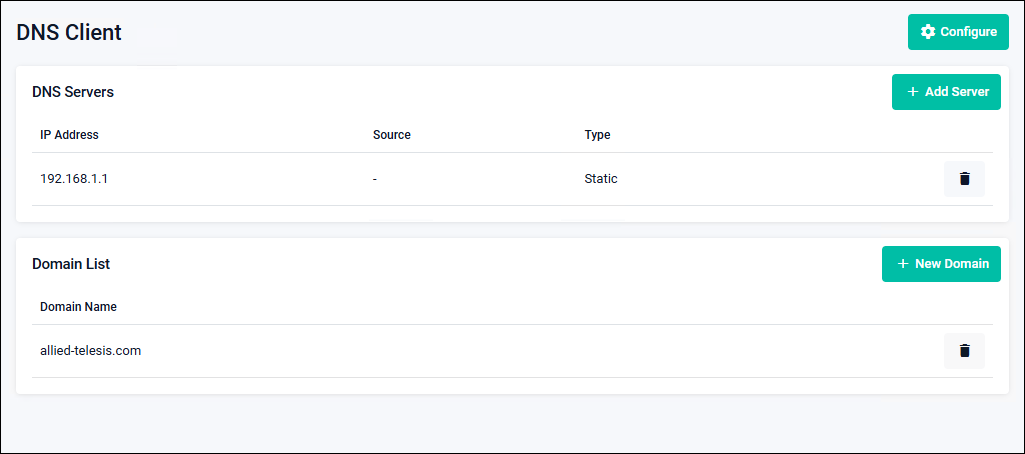
| "Configure" button | The Configure dialog opens to configure queries to the DNS server. |
| DNS Servers | |
|---|---|
| IP Address | The IPv4/IPv6 Address of the DNS server is displayed. |
| Source | The name of the interface that learned the DNS server address is displayed. |
| Type | Whether the DNS server was learned dynamically (Dynamic) or registered manually (Static) is displayed. |
| "Trash icon (Delete)" button | Deletes the DNS server registration. A confirmation dialog appears before deletion. |
| "Add Server" button | The New Server dialog opens to add a DNS server. |
| Domain List | |
| Domain Name | The registered domain name is displayed. |
| "Trash icon (Delete)" button | Deletes the registered domain. A confirmation dialog appears before deletion. |
| "New Domain" button | The New Domain dialog opens to add a domain to the search domain list used for DNS queries. |
Configure
Configures queries to the DNS server.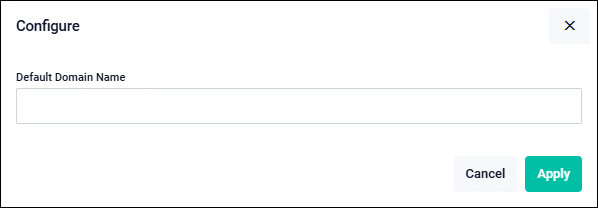
| Default Domain Name | Enter the default domain name used for DNS queries. |
| "Cancel" button | Returns to the DNS Client page without saving the DNS server query settings. |
| "Apply" button | Saves the DNS server query settings and returns to the DNS Client page. |
New Server
Adds a DNS server to be used for name resolution queries.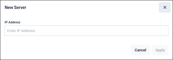
| IP Address | Enter the IPv4 or IPv6 Address of the DNS server. |
| "Cancel" button | Returns to the DNS Client page without adding a DNS server. |
| "Apply" button | Adds a DNS server and returns to the DNS Client page. |
New Domain
Adds a domain to the search domain list used for DNS queries.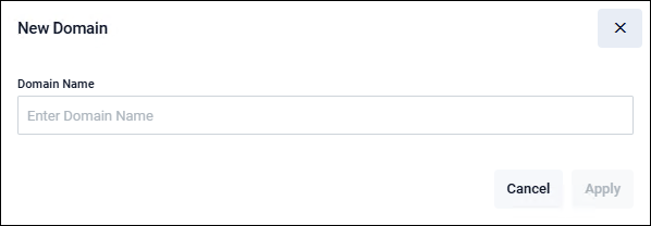
| Domain Name | Enter the domain name to register in the search domain list used for DNS queries. |
| "Cancel" button | Returns to the DNS Client page without adding a domain. |
| "Apply" button | Adds a domain and returns to the DNS Client page. |
User Management
Allied Telesis Container Platform > User ManagementYou can view, add, delete, and modify the list of users who log in to the Allied Telesis Container Platform.
NoteWhen all users are deleted, login becomes unavailable. Be sure to retain the default user name "manager" or create a backup user account. Take sufficient care in user management.
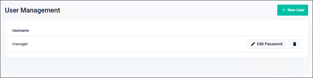
| User Name | The user name is displayed. |
| "Edit Password" button | The Edit password dialog opens to change the user's password. |
| "Trash icon (Delete)" button | The user is deleted. A confirmation dialog appears before deletion. |
| "New User" button | The Create new user dialog opens. |
NoteDuplicate user names cannot be registered.
Create new user
This is the dialog for adding a new user.NoteDeleting the default user name "manager" makes login impossible. Creating a user for backup purposes is recommended.
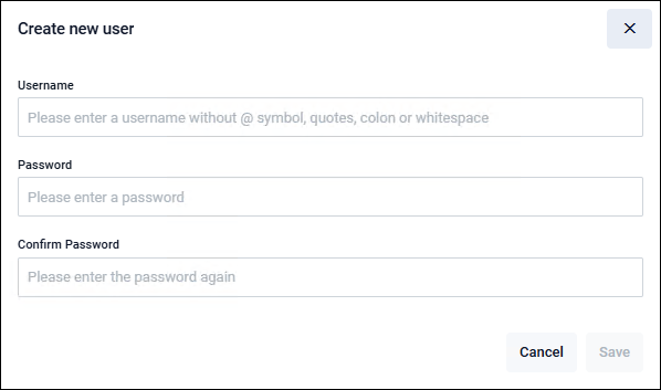
| User Name | Enter the user name for the new user. Allowed user name length: 1 to 64 characters. Only single-byte alphanumeric characters and symbols (-, _) are allowed. The first character must be a letter or a symbol. Case-sensitive. The user names "root", "daemon", "nobody", "sshd", and "httpd" are reserved and cannot be used. |
| Password | Enter the password for the new user. Allowed password length: 1 to 31 characters. Only single-byte alphanumeric characters and symbols ( " # $ % & ' ( ) * + , - . / |
| Confirm Password | Re-enter the password for the new user to confirm. |
| "Cancel" button | Returns to the User Management page without adding a new user. |
| "Save" button | Adds a new user and returns to the User Management page. |
Edit password
This is the dialog for changing the password of an existing user.NoteIf all user passwords are forgotten, login becomes impossible. Take proper care when managing passwords.
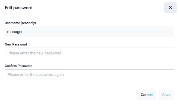
| Username (readonly) | The user name to be edited is displayed. |
| New Password | Enter the new password. Allowed password length: 1 to 31 characters. Only single-byte alphanumeric characters and symbols ( " # $ % & ' ( ) * + , - . / |
| Confirm Password | Re-enter the new password to confirm. |
| "Cancel" button | Returns to the User Management page without changing the password. |
| "Save" button | Change the password and return to the User Management page. |
System
Allied Telesis Container Platform > SystemEach page under the System menu provides basic information about the Allied Telesis Container Platform. You can also access File Management.
File Management
Allied Telesis Container Platform > System > File ManagementYou can view the list of files and perform file operations.
NoteDeleting or modifying files required by the Allied Telesis Container Platform or the AT-RADgate application may prevent them from starting.
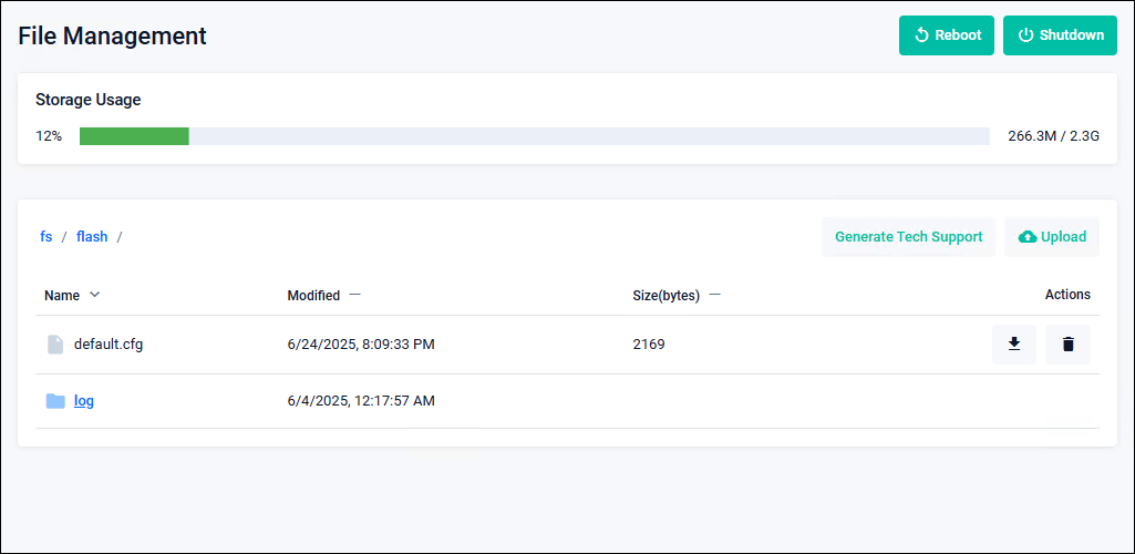
| "Reboot" button | Restart the Allied Telesis Container Platform. After the restart is complete, the login page appears. |
| "Shutdown" button | Shut down the Allied Telesis Container Platform. |
| "Upload" button | Upload a file. |
| "Generate Tech Support" button | A file for technical support is output. This is intended for cases where checking internal information is required, such as for troubleshooting, so consult our technical staff before using it. NoteWhen obtaining technical support information, if the message "Generate tech support file for this device" disappears but the generated file does not appear in the file list, reload your web browser. |
| "Down Arrow icon (Download)" button | Download a file. |
| "Trash icon (Delete)" button | Delete a file. A confirmation dialog appears before deletion. |
Container Services
Allied Telesis Container Platform > System > Container ServicesDisplay the status of the Allied Telesis Container Platform and the available applications.
NoteConfiguring or launching multiple instances of the same application from this page is intended for troubleshooting purposes.
For normal operation, follow the steps in Configuring and Starting the AT-RADgate application.
NoteIf the CPU Load, Memory, or Storage bar turns red, delete the application.
Note"Image server poll interval" is not supported. Do not change this setting from 'Disabled'.
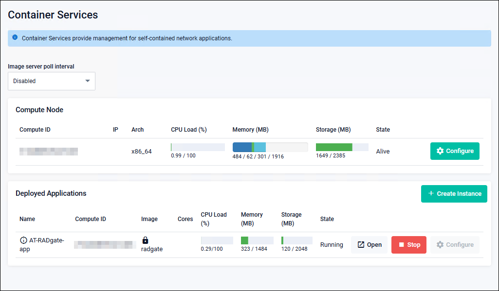
| "Configure" button | NoteConfiguration of Compute Node is not supported. |
Logging
Allied Telesis Container Platform > System > LoggingYou can view local logs.
You can switch between Buffered and Permanent logs, search and filter the logs, and update to the latest information using the "Refresh" button.
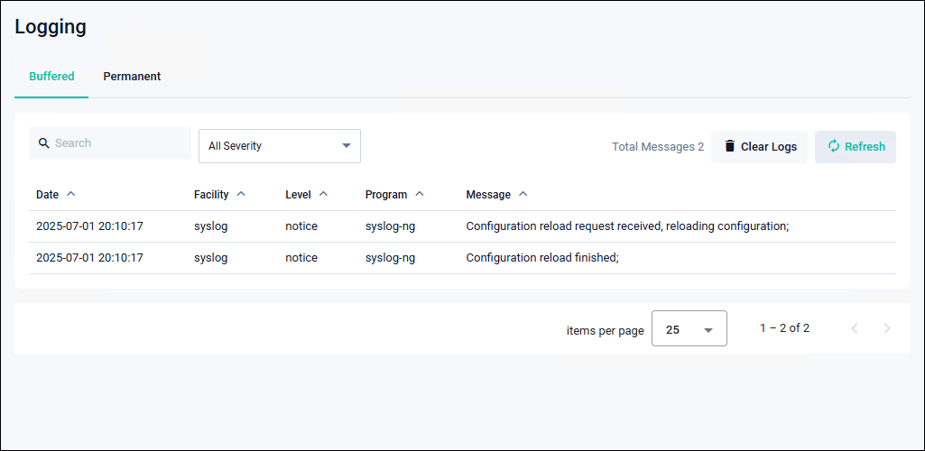
| Buffered | Logs stored in runtime memory are displayed. |
| Permanent | Logs stored in flash memory are displayed. |
| "Clear Logs" button | Delete logs. A confirmation dialog appears before deletion. |
| "Refresh" button | Update to the latest information. |
NoteBoth Buffered and Permanent logs can store up to 5 MBytes (approximately 40,000 to 50,000 entries).
Monitor
Allied Telesis Container Platform > System > MonitorYou can check detailed usage of memory, CPU, and storage.
NoteYou can check detailed usage of memory and CPU.This page is intended for situations where internal information needs to be checked, such as during troubleshooting.
Pressing either "Record" or "Start" activates the monitoring process and begins data collection. However, depending on the configuration values, this may affect currently running functions. Contact our technical support before using this page.
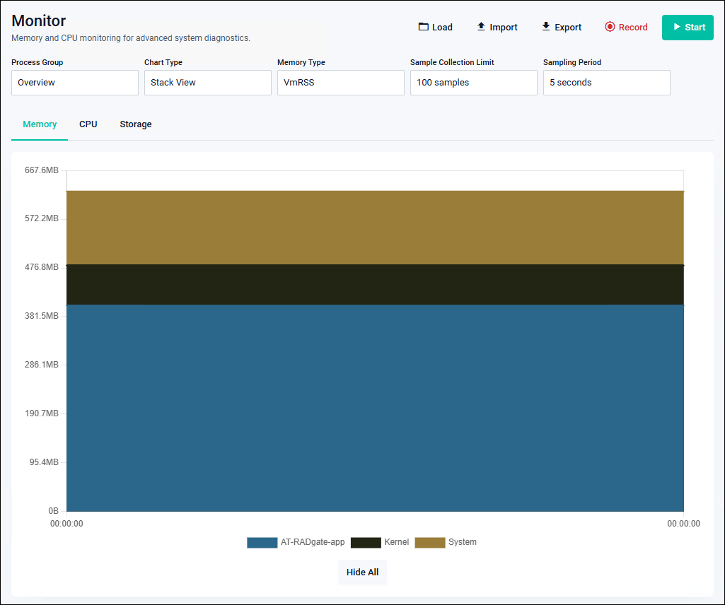
| "Load" button | Loads sample files stored on the device. |
| "Import" button | Uploads and loads sample files from a PC or other device. |
| "Export" button | Downloads samples stored in the browser's memory as files to a PC or other device. |
| "Record" button | Starts collecting samples (saved as files on the device). During collection, GUI timeout is disabled for the duration of “Sample Collection Limit × Sampling Period”. |
| "Start" button | Starts collecting samples (stored in the browser's memory). During collection, GUI timeout is disabled for the duration of “Sample Collection Limit × Sampling Period”. |
| Sample Collection Limit | Number of data acquisitions |
| Sampling Period | Data acquisition interval |
Service Management
Allied Telesis Container Platform > System > Service ManagementYou can check and change HTTP/HTTPS ports.
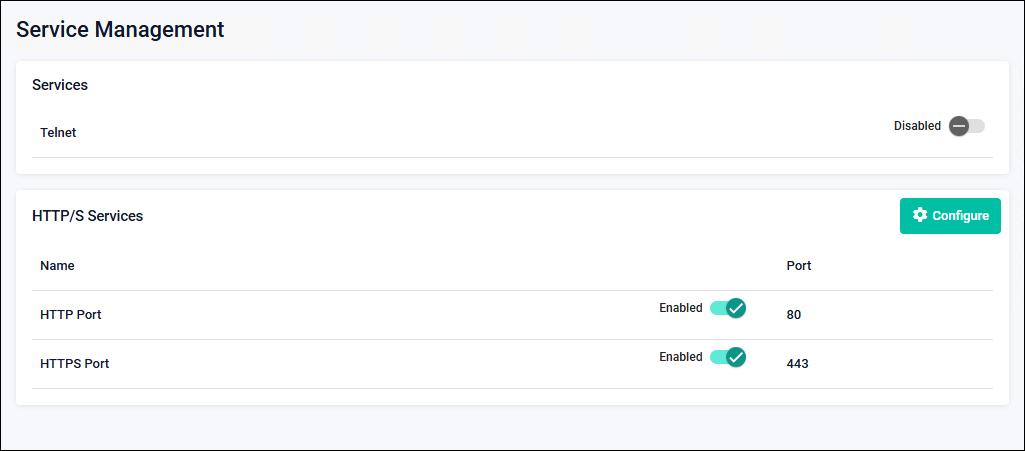
| HTTP Port | The current HTTP port setting is displayed. |
| HTTPS Port | The current HTTPS port setting is displayed. |
| "Configure" button | Changes the HTTP/HTTPS port settings. |
| Enabled/Disabled slide button | Toggles enable/disable for HTTP and HTTPS ports.NoteTelnet service is not supported. |
SSH
Allied Telesis Container Platform > System > SSHNoteYou can enable or disable login control for the SSH server (allow/deny), and view or register the list of allowed and denied users.SSH is not supported.
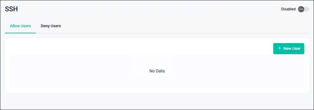
| Allow Users List tab | Configures and displays the list of users allowed to log in to the SSH server. |
| Deny Users List tab | Configures and displays the list of users denied access to the SSH server. |
| User | Displays the usernames that are allowed or denied. |
| Host | Displays the hostname or IP Address of the login source. |
| "New User" button | Displays the New User dialog. |
| "Delete" button | Deletes the selected user from the list. |
| Enabled/Disabled slide button | Toggles enable/disable for the SSH service. |
New User
This is the dialog for adding users to the Allow/Deny Users list.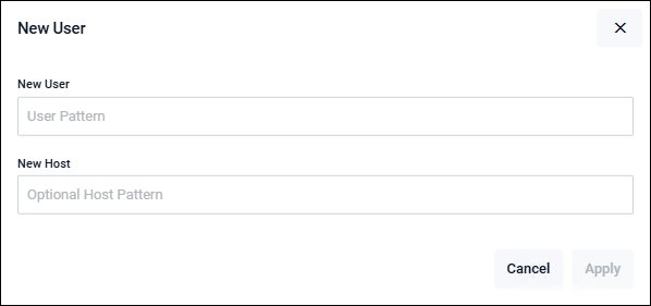
| New User | Enter the username pattern. |
| New Host | Enter the hostname pattern. |
| "Cancel" button | Return to the list page without saving or applying the settings. |
| "Apply" button | Save and apply the settings, then return to the list page. |
Time
Allied Telesis Container Platform > System > TimeYou can manually configure the system clock and set up NTP.
Set the date and time using the local time, and click the "Apply" button to update the system clock.
To use an external NTP server for time synchronization, click the "Add" button in the NTP Server section to add an NTP synchronization target.
To configure this product to operate as an NTP server, click the "Advanced Settings" button and set the stratum level in the Configure Global NTP settings dialog.
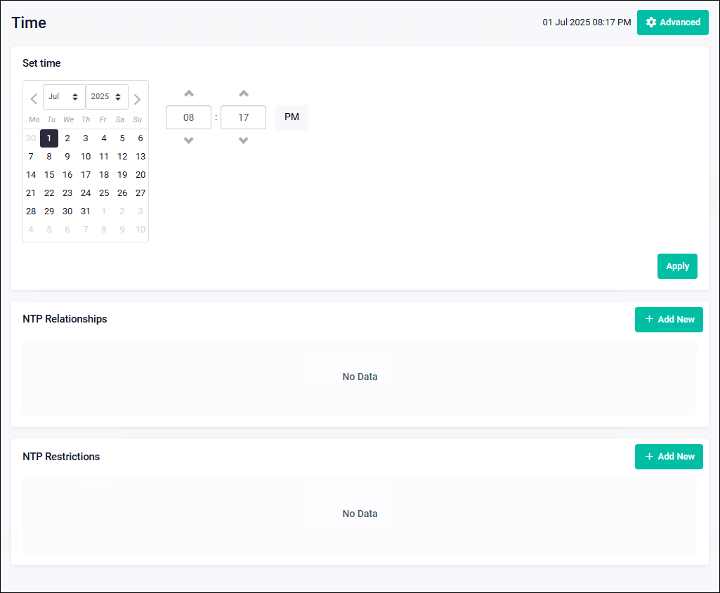
| Set time | Specify the date and time when you want to change the system clock. Clicking the "Apply" button updates the system clock with the specified date and time. |
| NTP Relationships | A list of NTP synchronization targets is displayed. Clicking the "Add" button displays the dialog for adding an NTP synchronization target. Clicking the delete button on the far right removes the corresponding synchronization target. |
| NTP Restrictions | A list of NTP Restrictions settings is displayed. Clicking the "Add" button displays the New NTP Restriction dialog. Clicking the delete button on the far right removes the NTP Restrictions setting. |
| "Advanced Settings" button | The Configure Global NTP settings dialog is displayed. |
Add an NTP synchronization target
This is a dialog for adding a new NTP synchronization target.NoteWhen an NTP synchronization target is added and time synchronization with the NTP server is successful, this product also begins operating as an NTP server. Therefore, when enabling the NTP client function in a location that may be vulnerable to attacks from malicious third parties, it is recommended to use filtering features such as the New NTP Restriction to allow only necessary NTP communication.
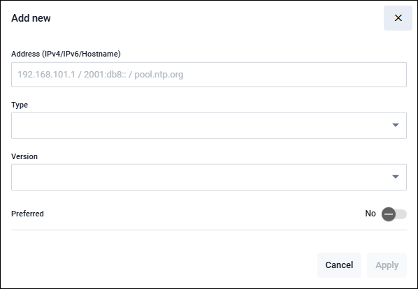
| Address (IPv4/IPv6/Hostname) | Enter an IPv4 Address, IPv6 Address, or hostname. When specifying an FQDN, you must register the DNS server address on the DNS Client page. |
| Type | Select the type of synchronization target from Server (NTP server), Peer (peer configuration), or Pool (pool server). |
| Version | Select the NTP protocol version from 1, 2, 3, or 4. |
| Preferred | When multiple NTP synchronization sources are registered, select “No” if this NTP source is not to be used preferentially, or “Yes” if it is to be used preferentially. |
| "Cancel" button | Return to the Time page without adding an NTP synchronization source. |
| "Apply" button | Add an NTP synchronization source and return to the Time page. |
New NTP Restriction
This dialog is used to add access control settings for the NTP server of this product.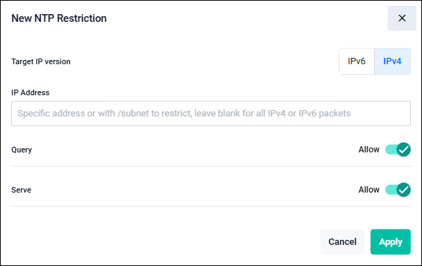
| Target IP version | Select the IP version. |
| IP Address | Specify the source address or subnet. Leaving this field blank specifies all addresses (any). |
| Query | Select whether to allow or deny control information queries from the source. |
| Serve | Select whether to allow or deny time queries from the source. |
| "Cancel" button | Return to the Time page without adding NTP access control settings. |
| "Apply" button | Add NTP access control settings and return to the Time page. |
Configure Global NTP settings
This dialog is used to configure general NTP settings.By setting the NTP stratum level, this product can be configured to operate as a standalone authoritative NTP server even if it is not synchronized with other NTP servers (operating at stratum levels 1 to 15).
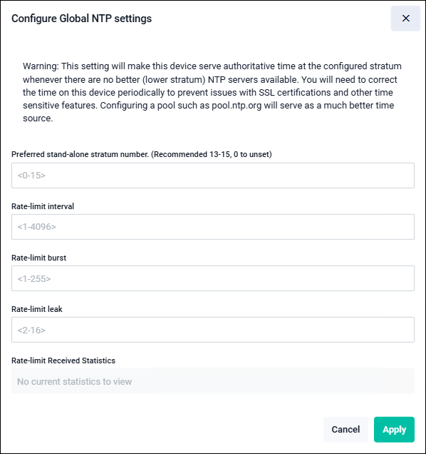
| Parameters for configuring this product to operate as a standalone authoritative NTP server | |
| Preferred stand-alone stratum number. | Enter a value between 0 and 15. A value of 1 indicates the highest stratum level and the most accurate time source. Entering 0 deletes the standalone NTP server settings. |
| Parameters for the NTP receive rate limiting feature | |
| Rate-limit interval | Minimum acceptable receive interval (seconds) |
| Rate-limit burst | The number of packets allowed to be received in bursts when the actual receive rate exceeds the configured interval value. |
| Rate-limit leak | When the actual receive rate exceeds both the interval and burst settings, specify the ratio of packets to be randomly allowed as “1 out of leak”. For example, if this parameter (leak) is set to 4, one out of every four packets is randomly allowed on average, even when the configured receive rate is exceeded. |
| Rate-limit Received Statistics | Statistics for the receive rate limiting feature are displayed. |
| "Cancel" button | Returns to the Time page without changing the Global NTP settings. |
| "Apply" button | Returns to the Time page after changing the Global NTP settings. |
Information
Allied Telesis Container Platform > System > AboutYou can view basic information about the Allied Telesis Container Platform.
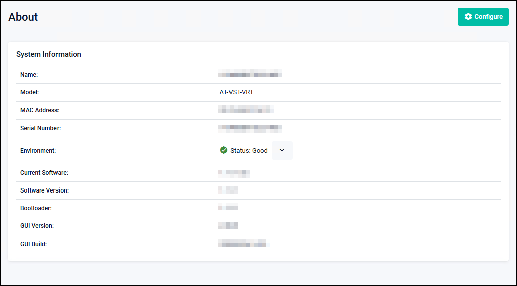
| Name | The host name is displayed. |
| Model | VST-VRT is displayed. |
| MAC Address | The MAC Address of this product is displayed. |
| Serial Number | The serial number of this product is displayed. |
| Environment | The overall status of the operating environment is displayed. Clicking the downward arrow displays “VST-VRT”. |
| Current Software | The currently used firmware image file is displayed. |
| Software Version | The firmware version currently in use is displayed. |
| Bootloader | The bootloader version is displayed. |
| GUI Version | The GUI version currently in use is displayed. |
| GUI Build | The GUI build currently in use is displayed. |
| "Configure" button | The Configure System Settings dialog opens. |
Configure System Settings
This dialog is used to configure system information.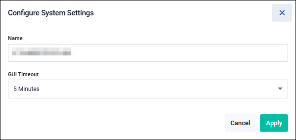
| Name | Enter the host name. |
| GUI Timeout | Specify the timeout duration for the Web GUI. |
| "Cancel" button | Return to the list page without saving or applying the settings. |
| "Apply" button | Save and apply the settings, then return to the list page. |
If no action is taken within 10 seconds, the system automatically returns to the login page.
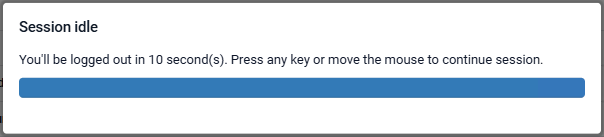
NoteThe GUI timeout setting is not saved on this product; it is stored in the browser’s local storage. If you change the browser or client device, or access the system using a URL with a different origin after setting the GUI timeout, the default setting is applied.
AT-RADgate
Allied Telesis Container Platform > AT-RADgateYou can configure and manage AT-RADgate application instances.
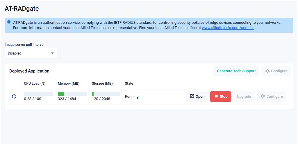
| Image server poll interval | Not supported. Use it while it remains disabled. |
| Deployed Applications | |
|---|---|
| Items displayed only when the application is not configured | |
| "Configure" button | Displays the Application Configuration dialog for initial configuration of the application instance. |
| Items displayed only after the application is configured | |
| "Generate Tech Support" button | A file for technical support is output. This is intended for cases where checking internal information is required, such as for troubleshooting, so consult our technical staff before using it. |
Information icon |
Hovering the mouse displays the Instance Information page as a popup. |
| CPU Load (%) | Displays the application's CPU usage. |
| Memory (MB) | Displays the application's memory usage (used / allocated). |
| Storage (MB) | Displays the application's storage usage (used / allocated). |
| Status | Displays the application status. |
| "Open" button | Opens the application's web GUI in a new browser window. Displayed only when the "State" is "Running". |
| "Delete" button | Deletes the application instance. Displayed only when the "State" is "Stopped".NoteDeleting the application removes the license and configuration information. Exercise caution when deleting the application. NoteIt is recommended not to delete the application unless it is required for troubleshooting or there are no plans to restore it. NoteDeleting the AT-RADgate application prevents the use of the existing license for future installations. Since reissuing the license is required, record the internal serial number after reinstallation and contact our sales engineer. |
| "Stop" button | Stops the application instance. Displayed only when the "State" is "Running". |
| "Start" button | Starts the application instance. Displayed only when the "State" is "Stopped". |
| "Configure" button | Displays the Application Configuration dialog for modifying the application instance settings. Enabled only when the application instance status is "Stopped". |
| "Upgrade" button | Displays the Application Configuration dialog for changing the application image version. Enabled only when the application instance status is "Stopped". |
NoteBefore creating an application instance or updating its version, delete unnecessary files and check the available storage space in the "Storage Usage" section of the File Management page.
Instance Information
Displays the configuration information of each application instance. Hovering over the information icon on the application page displays a popup.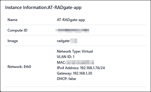
| Name | Displays the application instance name. |
| Compute ID | Displays the identifier (serial number) of the application runtime environment (Allied Telesis Container Platform). |
| Image | Displays the version of the application image. |
| DNS Server | DNS server address. Displayed only when a DNS server is specified in Application Configuration. |
| Network: ethX | |
| Displays information about the virtual interface. | |
| VLAN ID | Destination VLAN ID of the virtual interface. Displayed only when the network type is "Virtual". |
| Host Interface | The port on the Allied Telesis Container Platform directly connected to the virtual interface. Displayed only when the network type is "Physical". |
| MAC | MAC Address. Displayed only when the network type is "Virtual" and a "MAC Address (Optional)" is specified in Application Configuration. |
| IPv4 Address | IPv4 Address and subnet mask length configured for the interface. Displayed only when an IPv4 Address is specified in Application Configuration. |
| Gateway | Gateway Address. Displayed only when the Gateway Address is specified in the Application Configuration page. |
| Use DHCP | Indicates whether the IP settings of the interface are configured to be obtained from a DHCP server. |
Application Configuration
This dialog is used to perform initial setup and configuration changes for the AT-RADgate application instance. Displayed when the "Configure" button is clicked in the "Deployed Application" page. For details on the values to be set for each parameter, refer to Configuring and Starting the AT-RADgate application.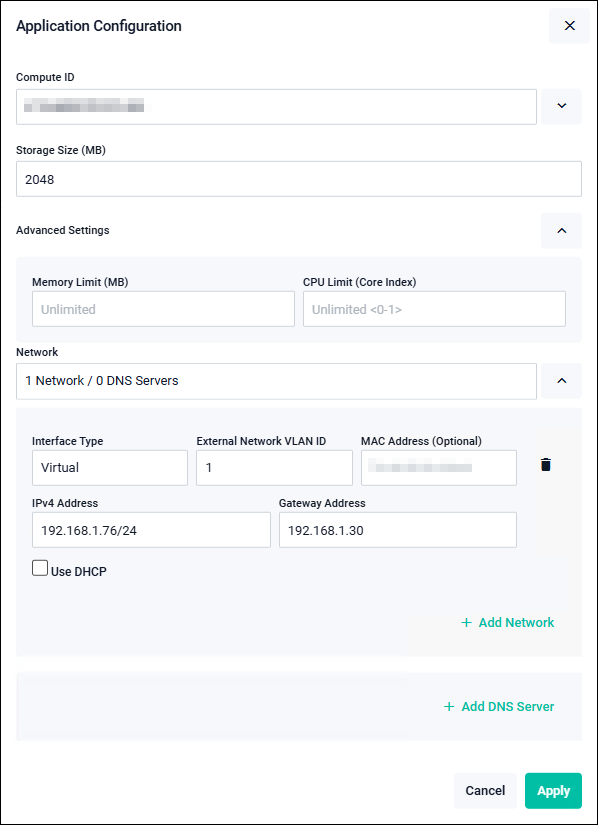
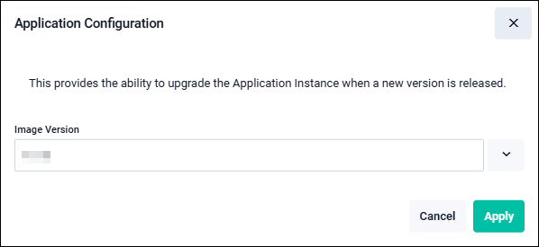
NoteOnly the Image Version field is displayed during version updates.
| Compute ID | Select "Local - The instance will be run on the device you are managing". |
| Image Version | Select the image version of the application instance. Displayed only during initial setup and version updates. |
| Storage Size (MB) | Specify the storage size to be allocated to the application. Enter the information according to Configuring and Starting the AT-RADgate application. |
| Advanced Settings | |
|---|---|
| Memory Limit (MB) | Configuration is usually not required. Use with the default setting (Unlimited). |
| CPU Limit (Core Index) | Configuration is usually not required. Use with the default setting (Unlimited). |
| Network / Network | |
You can add, delete, or configure virtual interfaces.NoteCreating multiple network interfaces is not supported. Use only one network interface. |
|
| Interface Type | Normally, use 'Virtual'. Virtual: Specify the External Network VLAN ID (required) and the MAC Address (Optional). In this case, multiple applications can be used on network ports that belong to the same VLAN ID. Physical: Allocates the application to a physical network port. Select the network port number to connect in the Host Interface. |
| External Network VLAN ID | Specify the VLAN ID to which the virtual interface connects (default value is 1). Displayed only when the interface type is "Virtual". |
| Host Interface | Select the port on the Allied Telesis Container Platform that is directly connected to the virtual interface. Displayed only when the interface type is "Physical". |
| MAC Address (Optional) | Enter a MAC Address if you want to manually specify one for the virtual interface. Automatically configured if not specified. Displayed only when the interface type is "Virtual". |
| Use DHCP | When checked, the IP Address assigned by the DHCP Server is used. When unchecked, the IPv4 Address and Gateway Address are set manually. When using DHCP, ensure that the environment allows IP Address acquisition from the DHCP server. |
| IPv4 Address | Enter the IPv4 Address and subnet mask length to be configured for the virtual interface. |
| Gateway Address | Enter the default gateway address. |
| "Add Network" link | Add a configuration section for the virtual interface. |
| "Trash icon (Delete)" button | Delete the configuration for the corresponding virtual interface. |
| Network / DNS Server | |
| You can add, delete, or configure DNS server addresses used by each application. | |
| "Add DNS Server" link | You can add, delete, or configure DNS server addresses used by each application. |
| DNS Server | Enter the address of a DNS server that can communicate.NoteIf a DNS Server address is configured, ensure that it is reachable. |
| "Trash icon (Delete)" button | Delete the corresponding DNS server address. |
| "Cancel" button | Return to the previous page without changing the application settings. |
| "Apply" button | Return to the previous page after changing the application settings. |
02 Oct 2025 12:05