Remote Monitor
The Remote Monitor feature allows you to monitor the aggregate status of wireless LAN controllers of AlliedWare Plus devices that are communicable from the AWC plug-in, as well as its wireless APs.
For the number of APs that can be managed by the Remote Monitor, please refer to Overview > What is the AWC Plug-in > Support Limits.
NoteWhen using the Remote Monitor feature, direct management of APs is not supported.
NoteFor information on configuring the wireless LAN controller of AlliedWare Plus devices, please refer to the user guide of the respective models.
NoteDepending on the CPU load and network communication conditions, it may not be possible to display all the log information sent by the wireless LAN controllers.
NoteThe heat map displayed on the Vista Manager of the wireless LAN controller and the map displayed on the remote monitor may not render the wireless output in the same way. Please refer to the rendition on the remote monitor, since the AWC Plug-in calculates more precisely and closer to the actual environment.
NoteThe heatmap calculates the radio signal strength at a given point from an AP's transmit power and the distance between the AP and the point. Because it assumes that there are no obstacles and reflection between the AP and the point, the actual radio signal strength may differ from the heatmap's calculation.
NoteAmong the map names set in Vista Manager, the following symbols will be displayed as underscores (_).
\ / : * ? " < > | . #
NoteWhen using a remote monitor, the total file size of the floor maps (including the file size of the background images) set in Vista Manager mini should be less than 4MB.
Remote Monitor
This page shows the monitoring status of the remote monitor (monitoring configuration to the wireless LAN controller).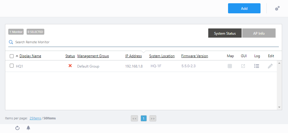
| Item Name | Description |
|---|---|
| Header | |
| "Add" button | The "Add Remote Monitor" dialog will appear. Here, you can add a remote monitor (monitoring configuration to the wireless LAN controller). |
"Gear" icon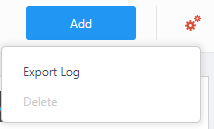
|
If you mouse over the gear icon, you will see Export Log and Delete sub-menu items. "Delete" is enabled by first ticking the checkbox(es) in the list of remote monitors.
|
| Remote Monitor | |
| Header | |
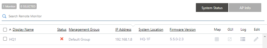
| X Monitor | Shows the total number of registered remote monitors (monitoring settings for the wireless LAN controller). |
| X SELECTED | The total number of selected (ticked) remote monitors is displayed. |
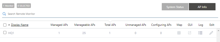
| System Status/AP Info switch button | Click to select the type of Remote Monitor information to display in the list. By default, system status information is displayed. |
| Search Remote Monitor | You can search for remote monitors. The Search field lets you enter a partial string to match. The screen displays entries with that string in one of the following fields: "Display Name", "Management Group", "IP address", "System location" or "Firmware Version". To remove the filter, delete the string from the Search field and press Enter. NoteThe search is case-sensitive. |
| System Info | |
|
|
| Display Name | Shows the display name of the Remote Monitor entered in the "Add Remote Monitor" dialog. |
| Status | Displays the operational status of the wireless LAN controller. |
| Management Group | Displays the administrative group of which the wireless LAN controller belongs to. |
| IP Address | Displays the IP address of the wireless LAN controller. |
| System Location | Displays the site of which the AMF device running the wireless LAN controller belongs to. |
| Firmware Version | Displays the firmware version that is running on the AlliedWare Plus device on which the wireless LAN controller is running. |
| Map | Click on the icon to bring up the Floor Map screen.NoteIn the Map view of the Remote Monitor, the update timer shown in the Floor Map Arranged AP List will run once, one minute after the page access. |
| GUI | Click on the icon to display the device web GUI for the AlliedWare Plus device running the wireless LAN controller. |
| Log | Click on the icon to display the Remote Monitor Logs screen. |
| Edit | Click on the icon to open the "Edit Remote Monitor" dialog. |
| AP Status | |
|
|
| Display Name | Shows the display name of the Remote Monitor entered in the "Add Remote Monitor" dialog. |
| Managed APs | Displays the number of wireless APs registered to the relevant wireless LAN controller with a status of "Managed". |
| Manageable APs | Displays the number of wireless APs that can be managed with the license applied to the relevant wireless LAN controller. |
| Total APs | Displays the number of wireless APs registered to the relevant wireless LAN controller. This includes wireless APs that are not under control. |
| Unmanaged APs | Shows the number of wireless APs registered with the relevant wireless LAN controller that have a status of "Unmanaged" or "Failed". |
| Configuring APs | Shows the number of wireless APs registered with the relevant wireless LAN controller that have a status of "Applying" or "Configuring". |
| Map | Click on the icon to bring up the Floor Map screen.NoteIn the Map view of the Remote Monitor, the update timer shown in the Floor Map Arranged AP List will run once, one minute after the page access. |
| GUI | Click on the icon to display the device web GUI for the AlliedWare Plus device running the wireless LAN controller. |
| Log | Click on the icon to display the Remote Monitor Logs screen. |
| Edit | Click on the icon to open the "Edit Remote Monitor" dialog. |
Add Remote Monitor
This dialog box lets you register the wireless LAN controller as a remote monitor.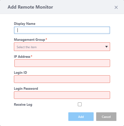
| Item Name | Description |
|---|---|
| Display Name | Edit the name of the Remote Monitor (monitoring configuration of the wireless LAN controller) that you have selected from the list. Should be 1 to 100 characters in length, with alphabets, numbers and symbols (including spaces). |
| Management Group | Specify from the drop-down list the management group to which the relevant wireless LAN controller and its wireless APs belong to. Only users with read access to the specified management group can see this Remote Monitor. |
| IP Address | Enter the IP address of the relevant wireless LAN controller.
|
| Login ID | Enter the admin username of the AlliedWare device for which the relevant wireless LAN controller is running on. |
| Password | Enter the admin password of the AlliedWare device for which the relevant wireless LAN controller is running on. |
| Receive Log | Check this box if you would like to receive logs from your wireless LAN controller. |
| "Add" button | Save your edits and register the Remote Monitor. |
| "Cancel" button | Discard your edits and close the dialog box. |
Edit Remote Monitor
This dialog box lets you edit the settings of a remote monitor.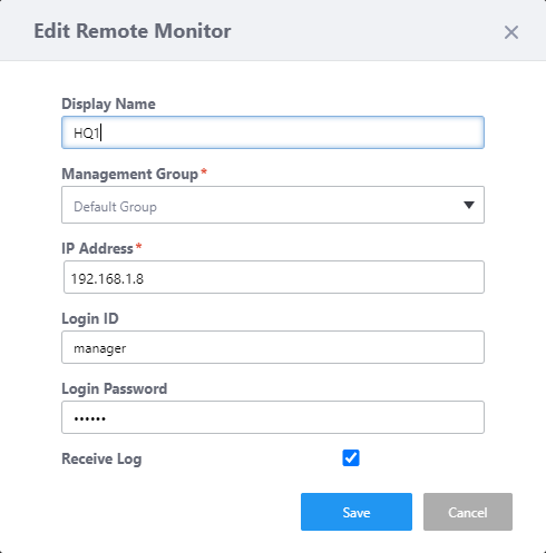
| Item Name | Description |
|---|---|
| Display Name | Edit the name of the Remote Monitor (monitoring configuration of the wireless LAN controller) that you have selected from the list. Should be 1 to 100 characters in length, with alphabets, numbers and symbols (including spaces). |
| Management Group | Specify from the drop-down list the management group to which the relevant wireless LAN controller and its wireless APs belong to. Only users with read access to the specified management group can see this Remote Monitor. |
| IP Address | Enter the IP address of the relevant wireless LAN controller.
|
| Login ID | Enter the admin username of the AlliedWare device for which the relevant wireless LAN controller is running on. |
| Password | Enter the admin password of the AlliedWare device for which the relevant wireless LAN controller is running on. |
| Receive Log | Check this box if you would like to receive logs from your wireless LAN controller. |
| "Save" button | Save your edits and update the remote monitor's registration. |
| "Cancel" button | Discard your edits and close the dialog box. |
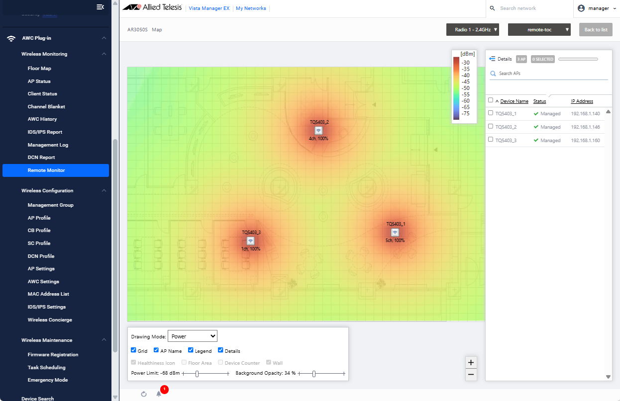
Floor Map
If the heat map is registered on Vista Manager mini of the wireless LAN controller, you may click the Map button in the remote monitor list to display it as a heat map in AWC plug-in format. This format uses formulas closer to the real environment.| Vista Manager mini style | AWC Plug-in style |
|---|---|
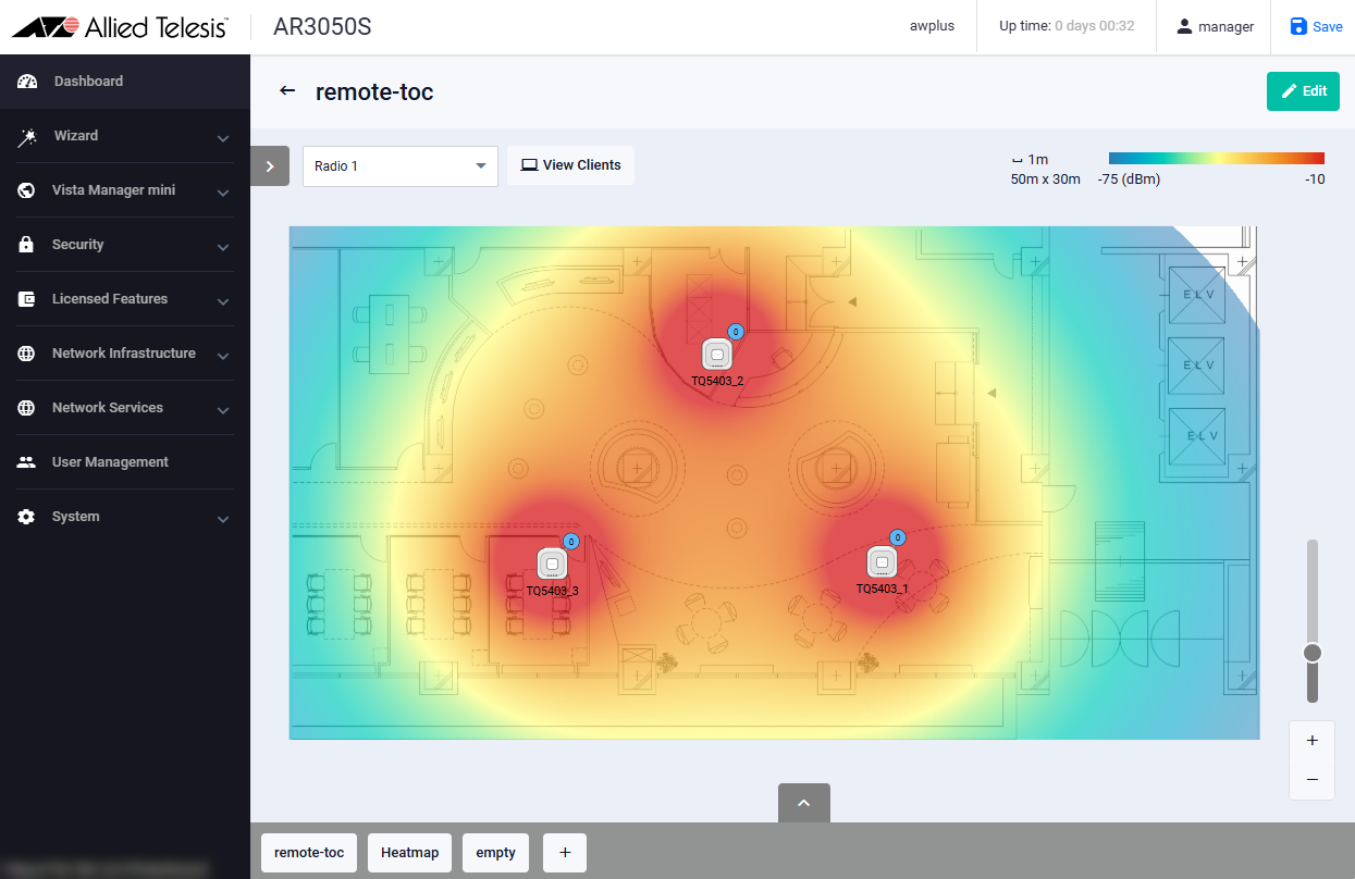
|
|
However, unlike "Floor Map Detail [Wireless Status View]" screen, the "Comfort Level" drawing mode cannot be selected. Only "Power" and "Channel" can be selected.
The floor map is displayed in the center of the Content section and a list of APs is shown on the right side of the Content section.
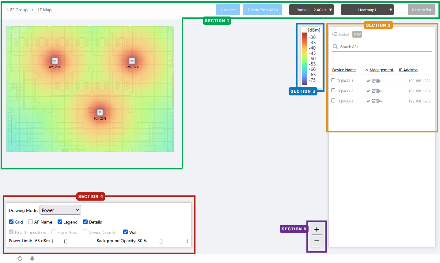
Section 1
| Item Name | Description |
|---|---|
| Radio dropdown menu | Lets you select a radio band to show on the map, from Radio 1, 2 or 3. |
| Heat map drop down menu | Selects the heat maps registered on the wireless LAN controller. |
| "Back to list" button | Returns to the Remote Monitor list screen. |
| Floor Map (Background) | Displays the map image registered on the heat map, on the wireless LAN controller. |
| Wireless AP Icon | Displays the AP icons registered on the heat map, on the wireless LAN controller. Below each icon, the channel and transmit power for the AP are displayed. Notes on icons:
|
Section 2
| Item Name | Description |
|---|---|
| Details | Clicking this shows the device's model, MAC address, AP Profile, tag, channel, radio strength, and the number of associated clients for each radio, as well as the Device name, Management Status and IP address that are shown on the non-detailed view. Clicking Details again returns you to the default non-detailed view. |
| X AP | Shows the number of APs placed on the floor map. |
| Refresh Timer | Disabled on floor map of remote monitor. |
| Search Wireless AP | Filter entries in the list by entering a partial string in the search box. The Search field lets you enter a partial string to match. The screen displays entries with that string in one of the following fields: "Device Name", "Management Status", "IP address", "MAC address" or "AP Profile" fields. To remove the filter, delete the string from the Search field and press Enter. NoteThe search is case-sensitive. |
| Filter by tag | Lets you filter APs with tags. Clicking tags uses tags to filter the list. Clicking them again removes the filter. Clicking "Clear filter" removes the filter for all tags. NoteTo select tags, you have to switch the list to detailed mode (by clicking "View Details"). |
| Tag | Disabled on floor map of remote monitor. |
| Device Name | The name of the managed device set by the wireless LAN controller is displayed. |
| Management Status | Shows the management status of the AP. |
| IP Address | Shows the AP's IP address. |
Section 3
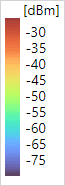
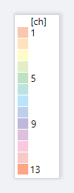
Shows the heatmap legend.
It shows the relationship between colors and signal strength or channels.
The legend can be made invisible or visible by using the checkbox in the floor map control section at the bottom of the page.
Color conventions depend on the floor map drawing mode.
- Power
- Channel
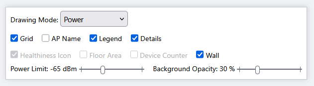
Section 4
On the floor map screen of the remote monitor, "Healthiness Icon", "Floor Area", "Device Counter", and "Wall" are irrelevant and disabled.
| Item Name | Description |
|---|---|
| Drawing Mode | Lets you select what to show on the heatmap. Options are power (signal strength) and channel. |
| Grid | Lets you enable or disable grid lines on the floor map. Checking this shows grid lines on the floor map. |
| AP Name | Whether to display the AP name above the AP icon. Check to display. |
| Legend | Lets you enable or disable the legend. Check to display. |
| Details | Check to display the list of placed APs. Check to display. |
| Power Limit | Specify the minimum signal strength to show in colors on the heatmap. |
| Opacity | Specify the opacity of the floor map background image. |
Section 5
Zoom In/Out buttons.
You can zoom in (+) or zoom out (-) of the floor map display. You can also use the mouse wheel scroll to zoom in or out.

Arranged AP List (Detail)
Clicking "Details" at the top of the list of placed APs on the Floor Map page extends the list to show additional information such as Device Type and AP Profile.Information displayed on the list can be switched between "System info", "Radio info" and "Client info". By default, each AP's system information is displayed.
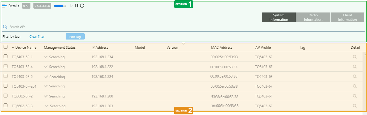
Section 1
| Item Name | Description |
|---|---|
| Details | Clicking "Details" again on the extended list shrinks the list to its default size. |
| X AP | Shows the number of wireless APs placed on the floor map. |
| Refresh Timer | Disabled on floor map of remote monitor. |
| Search Wireless AP | The Search field lets you enter a partial string to match. The screen displays entries with that string in one of the following fields: "Device Name", "Management Status", "IP address", "MAC address" or "AP Profile" fields. To remove the filter, delete the string from the Search field and press Enter. NoteThe search is case-sensitive. |
| "System Information" button | Switches the list content to system information for the APs placed on the floor map. |
| "Wireless Information" button | Switches the list content to the wireless configuration of the APs placed on the floor map. |
| "Client Info" button | Switches the list content to the number of clients (per radio) connected to each AP placed on the floor map. |
| Filter by tag | Disabled on floor map of remote monitor. |
| "Tag" button | Disabled on floor map of remote monitor. |
Section 2
| Item Name | Description |
|---|---|
| System Info | |
| Checkbox | To edit tags for APs, use the checkboxes to select APs and then click the "Edit Tags" button. |
| Device Name | The name of the managed device set by the wireless LAN controller is displayed. |
| Management Status | Shows the management status of the AP. |
| IP Address | Shows the AP's IP address. |
| Model | Shows the model name of the AP. |
| MAC Address | Shows the device's MAC address. |
| AP Profile | Shows the number of AP Profile assigned to the AP. |
| Tag | Shows the tags set on the AP. |
| Radio info | |
| Device Name | Shows the name given to the AP. |
| Channel (Radio1) Channel (Radio2) Channel (Radio3) |
Shows the channel used on each radio band of the AP. |
| Tx Power (Radio1) Tx Power (Radio2) Tx Power (Radio3) |
Shows the transmit power for each radio band of the AP. |
| Client info | |
| Device Name | Shows the name given to the AP. |
| Associated Clients (Radio 1) Associated Clients (Radio 2) Associated Clients (Radio 3) |
Shows the number of clients (per radio band) connected to the AP. |
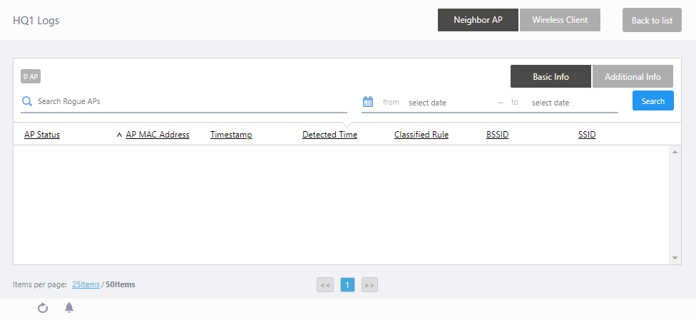
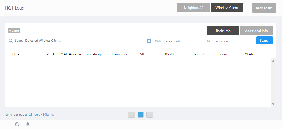
Remote Monitor Logs
This page displays the relevant logs of the wireless LAN controller that has been configured for remote monitoring.The screen title will appear as "(Remote Monitor's Display Name) Logs".
To view or update the contents of the log on the Remote Monitor Logs screen, specify the date and time in the "from" to "to" fields. Then click the "Search" button.
| Item Name | Description |
|---|---|
| Remote Monitor Logs Header | |
| Neighbor AP/Wireless Client switch button | Click to select the type of Remote Monitor information to display in the list. By default, the Neighbor AP information is displayed. |
| "Back to list" button | Click to return to the Remote Monitor List screen. |
| Neighbor AP List | |
|
|
|
| Neighbor AP List Header | |
| X AP | Displays the total number of neighbor APs detected by managed APs of the relevant wireless LAN controller. |
| Basic Info/Additional Info switch button | Click to select the type of neighbor AP information to be displayed in the list. By default, only basic information is displayed. |
| Search Rogue AP | You can search for neighbor APs. The Search field lets you enter a partial string to match. The screen displays entries with that string in one of the following fields: "AP Status", "AP MAC Address", "BSSID", "SSID", "Security Mode" or "Classified Rule". To remove the filter, delete the string from the Search field and press Enter. NoteThe search is case-sensitive. |
| from ... to | Lets you filter log entries by specifying a range of dates and times. |
| "Search" button | To filter log entries, click this button after entering a keyword or "from ... to" dates. |
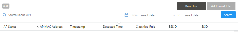
| Neighbor AP List Basic Information | |
|
|
| AP Status | Displays the status of the neighbor AP (managed or rogue). |
| AP MAC Address | Displays the MAC address of the neighbor AP. |
| Timestamp | Displays the date and time when the wireless LAN controller received information from the managed AP. |
| Detected Time | Displays the date and time when the AP under the control of the wireless LAN controller detected the neighbor AP. |
| Rogue Reason | Shows the reason to consider the detected neighbor AP a rogue. |
| BSSID | Displays the BSSID in the beacon frame. |
| SSID | Displays the SSID. |
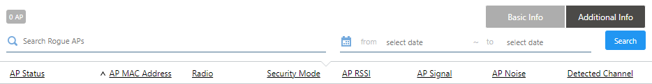
| Neighbor AP List Additional Information | |
|
|
| AP Status | Displays the status of the neighbor AP. |
| AP MAC Address | Displays the MAC address of the neighbor AP. |
| Radio | Shows the radio band used on the neighbor AP. |
| Security Mode | Displays the security mode used by the VAP that the neighbor AP is transmitting to. |
| AP RSSI | Displays the signal strength (in percent) from the neighbor AP. |
| AP Signal | Displays the Received Signal Strength Identifier (RSSI, in dBm) from the neighbor AP. |
| AP Noise | Displays the noise level (in dBm) of the channel being used by the neighbor AP. |
| Detected Channel | Displays the channel number used by the neighbor AP. |
| Associated Client | |
|
|
| Wireless Client List Header | |
| X Client | Displays the total number of clients detected by managed APs of the relevant wireless LAN controller. |
| Basic Info/Additional Info switch button | Select the type of client information to be displayed in the list. By default, only basic information is displayed. |
| Search Detected Wireless Client | Lets you filter the list of detected wireless clients. The Search field lets you enter a partial string to match. The screen displays entries with that string in one of the following fields: "Status", "Client MAC Address", "SSID", "BSSID", "NetBIOS Name" or "User Name"; or the client IP address. To remove the filter, delete the string from the Search field and press Enter. NoteThe search is case-sensitive. |
| from ... to | Lets you filter log entries by specifying a range of dates and times. |
| "Search" button | To filter log entries, click this button after entering a keyword or "from ... to" dates. |
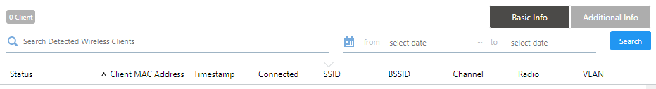
| Wireless Client List Basic Information | |
|
|
| Status | Distinguishes between connection and disconnection events for wireless clients. |
| Client MAC Address | Shows the MAC address of the client. |
| Timestamp | Displays the date and time when the wireless LAN controller received information from the managed AP. |
| Connected | Shows the estimated date and time when the client connected. |
| SSID | Displays the SSID of wireless network to which the client is connected to. |
| BSSID | Displays the BSSID of which the client is connected to. |
| Channel | Displays the channels that the wireless client is using. |
| Radio | Displays the radio bands of which the wireless client is connected to. |
| VLAN | Displays the VLAN of which the wireless client is connected to. |
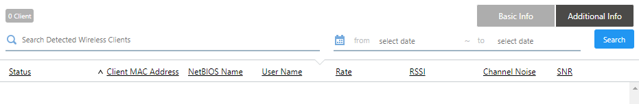
| Wireless Client List Additional Information | |
|
|
| Status | Distinguishes between connection and disconnection events for wireless clients. |
| Client MAC Address | Shows the MAC address of the client. |
| NetBIOS Name | Shows the NetBIOS host name of the wireless client. |
| Full Name | Shows the user name of the 802.1X authenticated wireless client. |
| Rate | Displays the data transmission rate (Mbps) of the wireless client. |
| RSSI | Displays the Received Signal Strength Indicator (RSSI) from the wireless client. |
| Channel Noise | Displays the noise level (in dBm) of the channel that the wireless client is using. |
| SNR | Displays the Signal-to-Noise Ratio (S/N ratio). A larger SNR means there is less noise influence. |
10 Nov 2025 11:46